


The picture is normal, but the PTZ does not move; the alarm input changes, but the remote relay does not act. These two types of problems cannot be judged only by looking at the optical port indicator light. A fiber optic transmission device converts electrical signals and sends them into the optical fiber, then restores the corresponding interface at the other end, but it will not automatically correct a wrong control protocol, and it will not turn a switch contact state into load power. First distinguish serial data from switch contacts, then check section by section along the input, transmission, output, and actuator.
1. What exactly does the control link transmit?
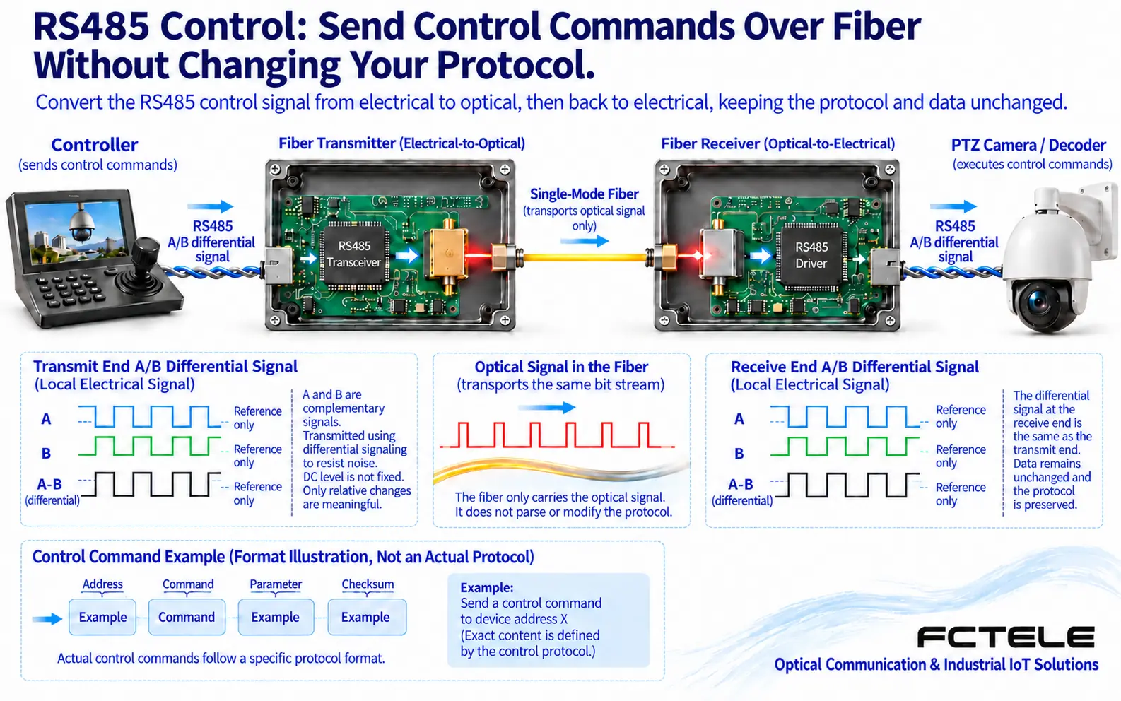
RS485 is an electrical interface specification. It describes how differential signals travel on wires, and it does not define commands such as “turn left” or “read temperature.” The controller first encodes the command into bytes, the serial port sends them at the agreed speed and format, and the RS485 transceiver turns them into differential electrical signals. A fiber optic transmission device with the corresponding data channel receives these signals, goes through internal processing and optical-to-electrical conversion, restores the serial interface at the far end, and then hands it to the PTZ decoder or another terminal.
Therefore, correct wiring is only the first step. Between the host controller, the relevant fiber optic transmission device settings, and the terminal, you also need to check the baud rate, data bits, parity bit, stop bits, as well as the protocol and device address used by the terminal. Transparent transmission usually tries to keep the byte content unchanged; it is not a “universal translator.” If the controller uses one PTZ protocol and the terminal only accepts another, correct action will not occur even if the optical link is intact. Specific devices that support protocol conversion are a separate matter and must be based on the model manual.
2. Why can control still fail when the picture is normal?
The video channel and the data channel may share the optical path, but they have their own input, output, and processing circuits. A normal picture shows that part of the transmission process is usable, but it does not mean the data wiring, configuration, and terminal protocol are all correct. Conversely, if control works, that also cannot prove that the video format, channel mapping, or input source have no problems. First record which services are normal and which are abnormal; this can quickly distinguish a common fault from a fault in a single branch.
For example, after a system replaces its PTZ, the PTZ cannot rotate, but the original video is still clear. Do not first replace the whole pair of fiber optic transmission devices. You should record the old and new PTZ models, check the new device address and serial port settings, and then use a compatible controller and a short cable for local verification. This is only an example of a troubleshooting order, not a real customer case. If it already fails locally, focus on the controller, protocol, or terminal; if it succeeds locally but fails across the optical fiber, then check the fiber optic transmission device data channel and the wiring at both ends section by section.
3. Avoid three misjudgments when checking RS485
First, do not treat one manufacturer’s A, B, or positive and negative markings as a universal wiring rule. Different devices may have different labeling habits, so you should confirm the signal definitions against both manuals. Two-wire half-duplex and four-wire interfaces also cannot be interconnected just by the shape of the plug; the transmit and receive directions, reference end, and terminal numbers all need to be checked. Change wiring only after power is off and permission is confirmed, and do not randomly short terminals while they are live as a test.
Second, a static voltage reading from an ordinary multimeter cannot independently prove that data is normal or damaged. Bus idle state, transmit and receive switching, biasing, and receiver design all affect the reading, and data changes may also be averaged out by the meter. When differential waveforms need to be observed, personnel with the proper conditions should use suitable instruments and safe measurement methods, to avoid the oscilloscope ground clip introducing an unexpected connection. Beginners can first do repeatable verification of protocol, address, short cable, and a known-good device.
Third, terminal resistors are not added at every node. They are used to reduce transmission line reflections, usually at the two ends of the bus trunk, and you must first confirm whether the device already has one built in. The resistance value and enabling conditions are determined according to the cable and device requirements; blindly adding more may increase the drive load. Try to maintain a continuous trunk and short branches, and understand shielding, reference ground, and protective grounding separately. When there is a risk of ground potential difference, use isolation and protection measures according to the design; do not rely on connecting a few extra wires and hoping for the best.
4. Switch contacts are not another kind of RS485
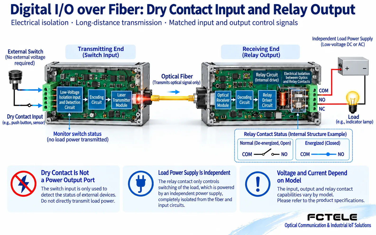
Switch contacts care about open, closed, or contact state, not continuous serial commands. Common dry contact inputs identify the state by detecting whether the contact is open or closed, but not all models accept the same kind of input: some use level input, and some have isolation or polarity requirements. Before checking the specifications, do not inject external voltage into the input end, and do not treat the power end as the alarm end.
If the remote output is a relay dry contact, its role is similar to a controlled switch: it drives the relay internally, the contact changes between open and closed, and the external load is still powered by its own power supply. The optical fiber transmits state information, not power to the warning light. The voltage, current, and load type allowed by the contact all have limits. Inductive loads such as motors and coils also involve energy release when they are disconnected, so appropriate drive and protection must be configured according to the design; you cannot look only at one number, the rated current.
5. How to do a safe small-scale verification
First back up the configuration, take photos to record the wiring, and apply for a test window. Isolate the production load from the test action, and under the conditions allowed by the manual, use a confirmed compatible low-voltage test loop to observe input changes, transmission status, and output contacts. Change only one condition at a time: first verify whether the input is recognized, then verify whether the remote output changes accordingly, and only then check the load and external power supply. If you do not have permission or cannot guarantee safety, stop at the reading and recording stage and leave it to professional personnel.
The Feichang FCP-F4pD8 product description lists switch contacts and RS232/422/485 and other configurations, as well as relay dry contact output. This information can help confirm the interface direction required by the system, but options such as channel count and network management still need to be checked against the order configuration. You cannot assume that because the same product series has multiple interfaces, the device in your hands has all of them, and you certainly cannot extend one model’s contact ratings to all fiber optic transmission devices.
6. After the action is restored, acceptance is still needed
After control is restored, verify whether the correct device performed the correct action, and whether there is an address conflict, reverse action, lost command, or reply timeout. For switch contacts, check the normal state, alarm state, state after power loss, and state after recovery. The observation duration should cover the load or environmental conditions where problems actually tend to occur; you cannot finish after pressing the button only once.
Record the final terminal definitions, protocol, address, serial port parameters, replaced parts, and test results. If the fault still remains, provide the models at both ends, wiring photos, time of occurrence, which services are normal, and the section-by-section test conclusions. This is more helpful for after-sales judgment than saying “the fiber optic transmission device is broken,” and it can also avoid repeated downtime. For a basic check of interfaces and backup power, refer to Common questions about using fiber optic transmission devices.
Data note: The technical mechanism refers to TI RS485 interface description; for the specific product, refer to Feichang FCP-F4pD8. The illustrations are general principle diagrams, not actual product photos, on-site measurements, or performance certifications.
Translated from the Chinese technical article. Source first published: 2021-07-16. Source last revised: 2026-10-13T17:22:03+08:00. Read the Chinese source
