


After installing a fiber optic video transmission equipment, if there is no picture, do not immediately assume the long fiber is broken, and do not repeatedly restart and hope for luck. First use a known-good short link to establish a baseline, then separately check the video source, power supply, optical path, and receiver output. This article uses an analog video fiber optic transmitter to explain debugging methods. Telephone, SDI, and Ethernet services need to be verified according to their own terminal and interface rules.
1. First confirm which layer the “no picture” occurs at
The camera has no output, the transmitter does not support the input format, the two ends are not matched, the optical path loss is too large, and the viewing device has selected the wrong input—all of these can appear as a black screen. They are at different stages, yet they give the user a similar intuitive result. Therefore, the first action in debugging is to record the device model, link structure, and site status, rather than first replacing the most expensive device.
Write the symptoms specifically: Is there no picture all the time, or does it occasionally drop out? Is only one channel abnormal, or are all channels abnormal? Rolling picture, color cast, snow, and complete loss of signal are not the same type of evidence. Record the time the abnormality occurs, the power and indicator light status, and whether there was external operation or weather change. If there is already a normal channel on site, keep it as a comparison object; do not change the entire system just to test once.
2. What a short-fiber baseline can rule out
Use a compatible, known-good video source and display end, together with transmitting and receiving devices matched to the model and a short fiber, to establish the simplest link. If this link works, it shows that this set of devices can complete transmission under the current configuration and service conditions. It cannot prove that any length of line, any video format, or all auxiliary channels are qualified; the conclusion of the baseline must be limited to the actual test conditions.
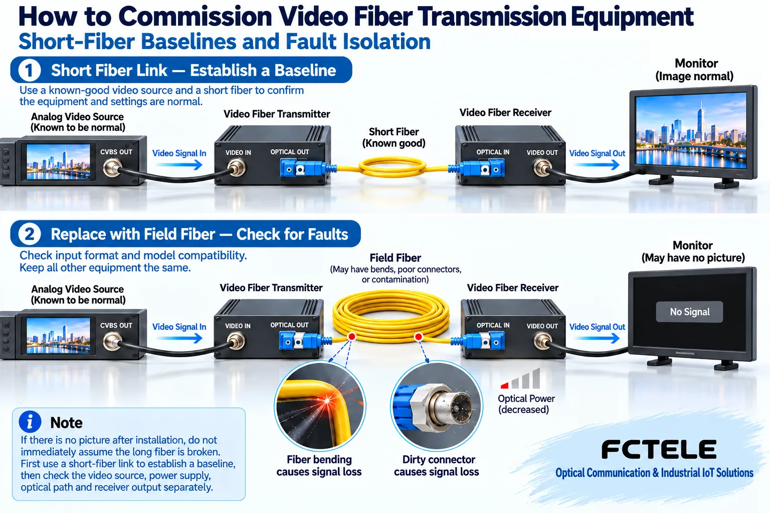
If the short link still fails, you also cannot directly judge that the hardware is damaged. First confirm the transmit and receive roles, video format, optical port pairing, power conditions, display device input, and necessary configuration. Known-good replacement devices help with comparison, but replacement must maintain compatible specifications; do not just find a similar-looking shell and plug it in. Some optical ports also need their receive upper limit checked under short fiber; do not ignore the allowed power range just because the distance is short.
3. On-site optical paths must be judged with evidence
Replace the short fiber in the baseline with the on-site fiber, keeping the other parts unchanged. When an abnormality occurs, check whether the line number is connected incorrectly, whether the connector is fully inserted, whether the patch cord is pinched, and whether the end face is contaminated. Dust may increase coupling loss, and bending may prevent part of the light from continuing along the fiber core; these problems may cause complete loss of connection or may appear only when conditions change, so they should not be ruled out by a single indicator light being on.
Received optical power is important evidence. It needs to be measured at the appropriate wavelength and with the instrument set up properly, and compared with the allowed range of that receiver. The optical budget must consider the line, connection points, and necessary margin, but you cannot work backward from the maximum transmission distance on the nameplate to conclude that the site will definitely work. An optical power meter measures the relevant power, while an OTDR is used to analyze line events; their uses are different, and one reading cannot be treated as proof that all services are qualified.
Before inspection, turn off the relevant light source according to procedures, and do not look into the optical port with the naked eye. Clean the end face with suitable tools and confirm again; do not wipe it with a sleeve or ordinary tissue. If there are doubts about connector polish type, single-mode versus multimode, and wavelength pairing, first check the model manual. SC or LC is only a shape clue; it cannot by itself prove that the fiber type and transmit/receive conditions are already correct.
4. Locate faults segment by segment along four observation points
The first observation point is the video input at the transmitter; confirm that the camera and coaxial cable really provide a compatible signal. The second is the optical output at the transmitter; confirm by an allowed method that there is a corresponding optical signal. The third is the optical input at the receiver; check the arriving power and link conditions. The fourth is the video output at the receiver; confirm the real picture on a compatible terminal. Each point answers a different question; if the previous point is normal, it does not mean everything after it is normal.
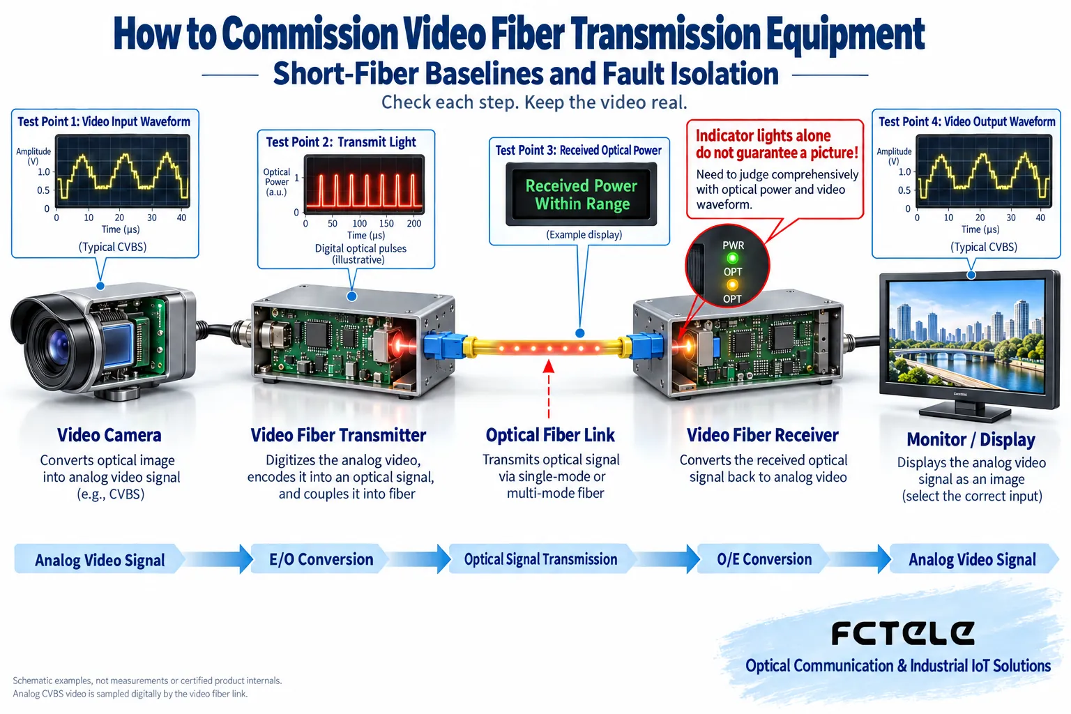
For example, if the received optical power is within the allowed range but there is still no picture at the output, continue checking whether both ends support the same service, whether the output channels correspond, and whether the recording end input is compatible. If the transmitter already has no qualified video input, repeatedly cleaning the far-end fiber will not solve the problem. The key to locating the fault is to first find the earliest observation point where the abnormality occurs, then check around that section, rather than replacing all cables at the same time.
5. Multiple channels and reverse services must be brought online separately
For a multi-channel video system, first verify one channel, then add channels one by one according to the numbering, to avoid mistaking a wrong channel connection for the device not working. For combined devices with pan-tilt control, audio, or telephone, also check the interfaces, directions, and parameters of these services themselves. If video is normal but control fails, check the reverse data and terminal protocol; there is no need to first suspect the video sampling circuit. A blinking light does not mean the control command has been correctly executed.
The debugging record should state what was changed each time. If you change the baud rate, replace the fiber, and replace the power supply all at once, even if it recovers, it is hard to know the real cause, and the fault may recur later. If there is a power supply or grounding abnormality that cannot be safely confirmed, it should be handled by personnel with the corresponding ability; do not treat shorting terminals, disassembling the power supply, or unplugging cards while powered as beginner debugging techniques.
6. After recovery, re-verification is still needed
After repair, retest under the conditions in which the abnormality originally occurred, such as multiple channels working at the same time, moving pictures, and the allowed temperature and power recovery scenarios. Archive the optical power before and after repair, end face inspection, channel correspondence, and service results. If it has only temporarily recovered, clearly record that the cause has not yet been determined; do not write it as permanently solved. The interfaces and options of specific Feichang Technology products can be checked through the official website details, and diagnostic conclusions should still be based on on-site evidence.
The most practical summary is: establish a working reference with a short link, replace one variable at a time on the on-site line, check input, optical path, and output in segments, and after recovery verify again with real services. In this way, you neither blame all problems on the fiber nor ignore terminal compatibility and service quality just because one light is on.
References Feichang Technology video fiber optic transmitter details and fiber inspection and cleaning materials. The illustrations are general mechanism diagrams; operations are subject to the device manual and safety procedures.
Translated from the Chinese technical article. Source first published: 2020-01-07. Source last revised: 2026-10-13T18:52:49+08:00. Read the Chinese source
