


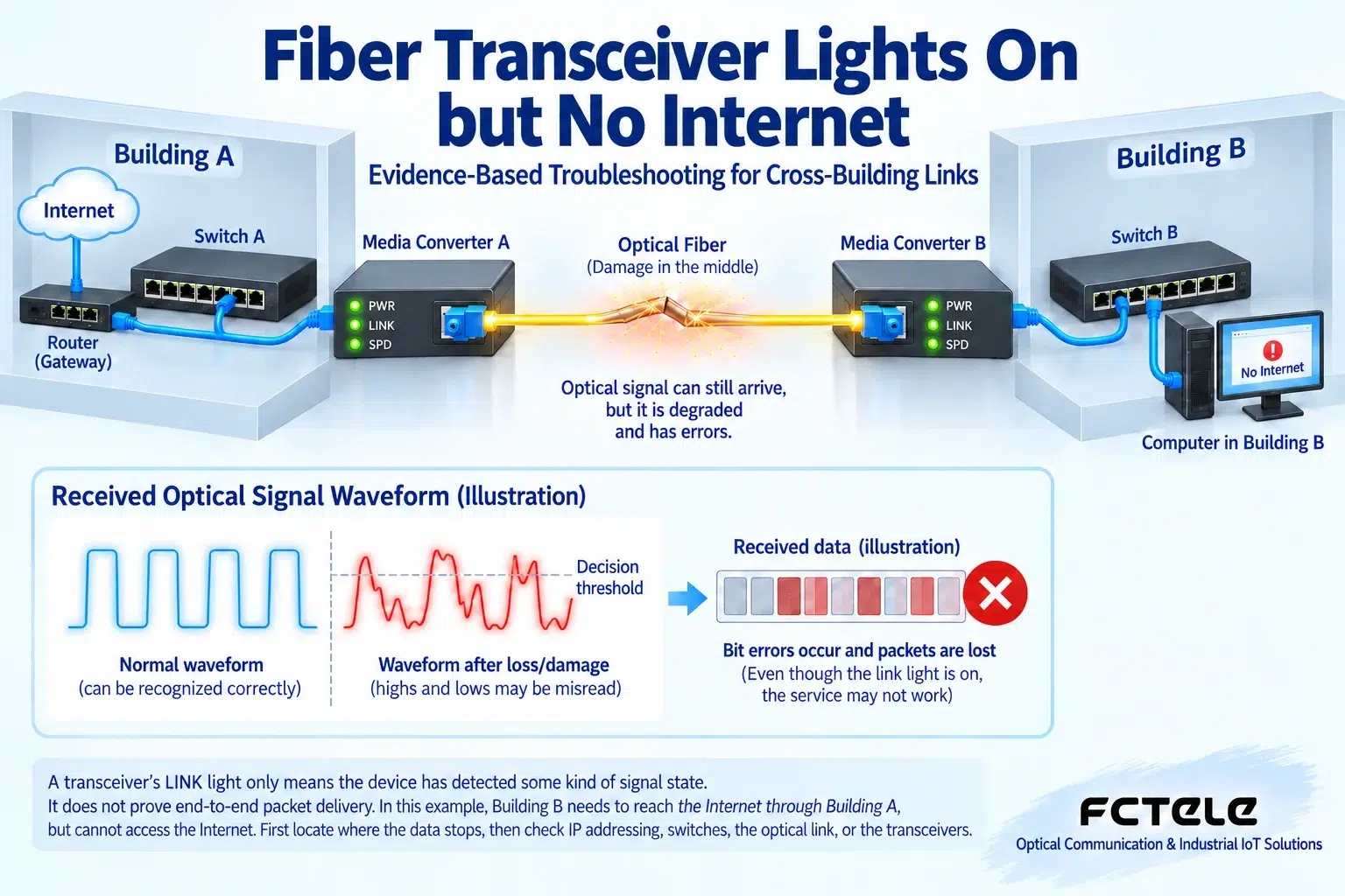
Transceiver lights being on only means the device has detected some kind of state; it does not mean that every step from the computer to the internet is working normally. When a cross-building LAN can access each other but cannot get online, you should first locate where the data stops, and then decide whether to check addresses, switches, the optical link, or the transceivers. This article uses a hypothetical two-building scenario to explain this, and does not treat guesses from past cases as general conclusions.
Draw the real path, do not skip the gateway
Assume that a computer in Building B reaches the gateway through a switch, Transceiver B, optical fiber, Transceiver A, and the Building A switch, and the gateway then connects to the external network. A gateway is the device that sends local network traffic to other networks, and a fiber transceiver does not take on this role. First confirm whether this path matches the actual wiring on site, and whether there are also VLANs, routing, a firewall, or a second uplink. Two computers in Building B being able to communicate with each other at most shows that part of the path between them is normal; it cannot prove that the cross-building path or the gateway is normal. Mark each port number and the models at both ends on the diagram, to avoid mistaking another service line for the target link during testing.
Why there may still be no valid data even when there is light
The optical receiver converts arriving light into a tiny current, which is then amplified and judged by the circuit. If there is noise, distortion, or unsuitable received power, the receiving end may detect a signal but cannot stably recover data. What an indicator light shows is determined by the device design: some indicate the physical link, some indicate activity, and some alarms are affected by fault pass-through. You cannot rule out the optical fiber just because Link and ACT are lit. Check the received power at both ends, interface error counters, and logs, and use a known-good short link as a comparison. Even if the optical power is within range, that does not mean all encoding, rate, and waveform conditions are correct, so it is one piece of evidence, not a certificate that the entire link is qualified.
Step 1: Confirm the computer’s address and local conditions
First record the IP address, subnet mask, default gateway, and domain name resolution settings. The mask determines which targets the computer treats as local neighbors, the gateway is responsible for forwarding across network segments, and domain name resolution is responsible for turning names into addresses. The three have different roles. Compare with a normal computer on the same network, and check whether there is an address conflict, an incorrect static setting, or a network card problem. Do not copy someone else’s IP and cause a new conflict. During testing, you can first access a clear internal address, then access the gateway, and then check an external address and domain name, to distinguish the problem step by step. If an external address is reachable but domain name access fails, the focus of investigation is different from when all targets are unreachable, and there is no need to immediately replace the fiber transceiver.
Step 2: Observe ARP, rather than guessing a virus from an occasional record
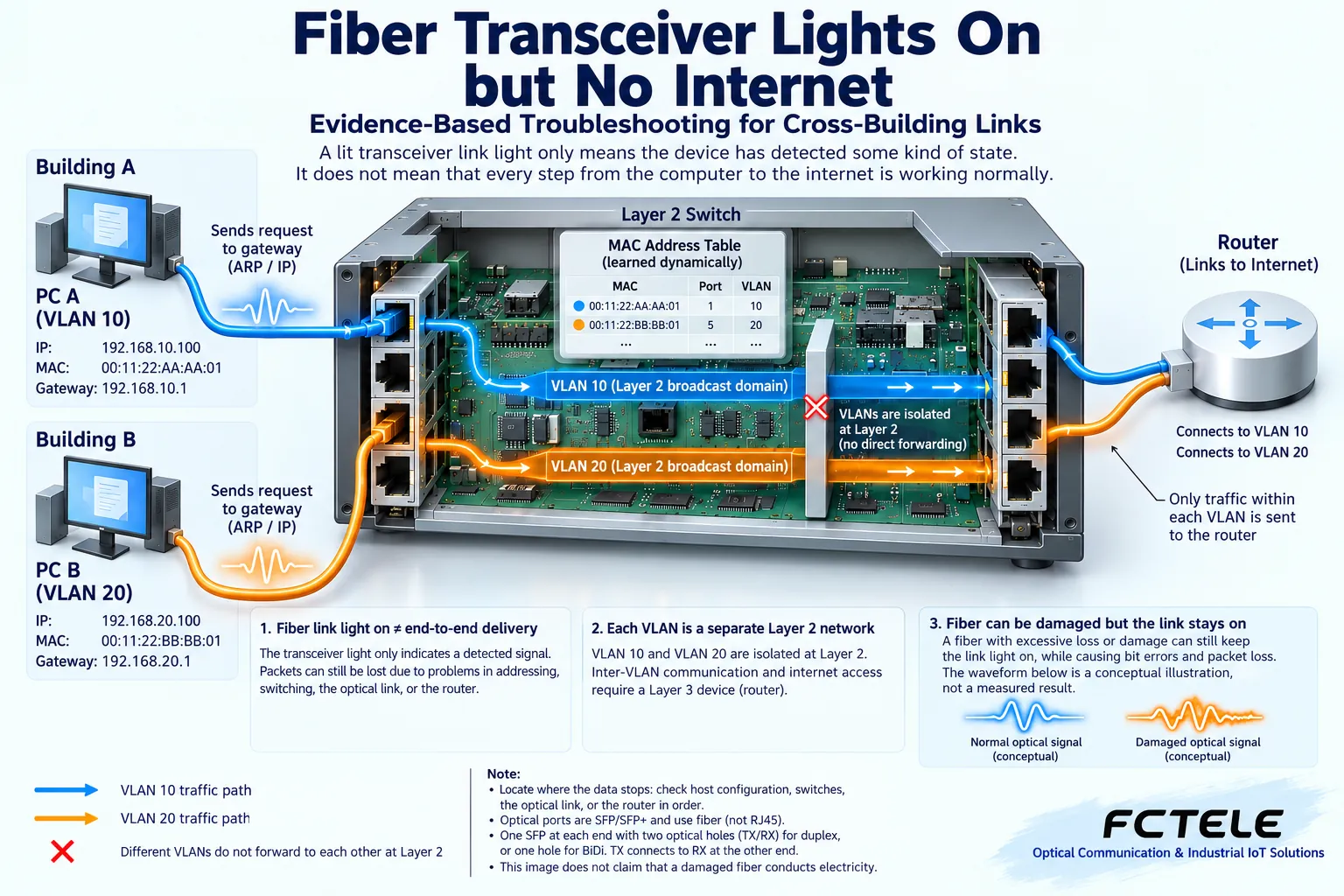
ARP is the mechanism in an IPv4 LAN for querying the hardware address of the next hop. After the computer knows the gateway IP, it usually must first obtain the corresponding MAC address before it can send frames on the local Ethernet. Occasionally obtaining a MAC cannot by itself prove that the link is healthy, nor can it prove that there is a virus. Old records, one-way communication, duplicate addresses, or switch status can all cause confusion. First record the phenomenon, then refresh the record within an authorized maintenance process and observe whether requests and responses cross the link. Compare the results of normal terminals, and pay attention to the actual deployment of the same gateway under different paths. If a security problem is suspected, packet captures and device logs should be collected and given to security personnel, and “cannot get online” should not be directly interpreted as an ARP attack.
Step 3: Check switch forwarding and VLAN boundaries
A switch usually sends known unicast frames to the corresponding port based on the destination MAC, while a VLAN divides the network on the same device into logically isolated ranges. When Building B can communicate internally but cannot communicate across buildings, it is sometimes because the tagging, allowed list, or access port configuration of the uplink port is inconsistent. Check the corresponding VLANs and port status at both ends, and confirm whether the service should pass through with a tag. Being able to log in to the management page does not mean the service VLAN configuration is correct; management traffic may take another logical path. Do not disable isolation or allow all VLANs through to try your luck without authorization. First save the configuration, check the design and normal ports, limit the scope of changes, and prepare a recovery plan.
Step 4: Replace by segments, keeping comparable conditions
During the maintenance window, first use a known-good terminal and a short network cable to test the corresponding port in Building A, then advance segment by segment along the path. If Building A is normal locally and Building B is abnormal, you can narrow the problem to the cross-building part and its configuration, but you still need to check whether the test terminal keeps the same settings. When replacing transceivers, check the rate, optical port, and pairing specifications; do not just pick up two devices that look the same. Change only one item at a time, and record the results before and after. In the original text, replacing both devices together and then recovering is not enough to determine which one was faulty, and it also cannot completely rule out the effect of power or connectors being reseated firmly. Scientific troubleshooting must acknowledge these variables that have not yet been separated.
How to write a complete troubleshooting record
It can be written as: during a certain period, internal access in Building B was normal but gateway probing failed; a test terminal on the same VLAN in Building A was normal; optical power and error counters at both ends were recorded; after replacing a specified short patch cord the result did not change; after replacing a compatible device at one end and keeping the original power supply, it recovered. Such a record allows others to reproduce and ask further questions, and contains more information than “the transceiver was broken and has been replaced.” If only the result of an overall replacement is available, you should also truthfully state which components were replaced, and that the root cause cannot yet be distinguished. Troubleshooting is not about finding a device to blame, but about building an evidence chain among phenomena, actions, and results. The signal and VLAN processes in the figure are illustrative for explanation, not a diagnosis of the on-site topology.
After restoring the network, you still need to verify applications
Finally, retest both directions across buildings, the gateway, domain name resolution, and the services users actually need. File transfer, video streaming, or industrial software have different connection, load, and timeout requirements, and a single successful Ping cannot represent full recovery. Observe a period of operation that covers the original fault conditions, and confirm whether error counters, reconnections, and alarms persist. Keep the original devices and configuration, mark them as pending inspection, and do not scrap them immediately without analysis. What users care about most is stable availability, not the light turning green. Checking step by step by layer can avoid mistakenly changing the gateway, security policies, and service isolation, and can also reduce the situation of repeatedly replacing parts without finding the cause.
Principle verification materials:Official material 1;Official material 2. The general mechanisms and examples in the text do not replace the manual for the corresponding model.
Translated from the Chinese technical article. Source first published: 2020-06-08. Source last revised: 2026-10-13T22:21:36+08:00. Read the Chinese source
