


Portable or field-deployed fiber optic transmission devices are used to carry the service signals supported by the equipment at a temporary site. Networking is still essentially about interface matching, optical path budget, and power supply reliability. It is not that just having a reel of fiber optic cable will automatically transmit all video, voice, and data. This article explains things for civil emergency and temporary communication scenarios, and makes no performance promises for unknown models.
First, list the on-site services as an interface checklist
A temporary command post, monitoring equipment, and a rear platform may use Ethernet, telephone, analog video, or serial interfaces. For each type of service, you should write down the direction, quantity, and format, which determines whether you use an integrated fiber optic transmission device or different transmission equipment. IP services on a network port and dedicated video ports are not at the same layer, and you cannot replace an interface description with a vague phrase like “supports images.” You also need to confirm whether the service equipment on both sides is compatible and who is responsible for encoding, display, or recording.
Point-to-point is the easiest way to establish a verifiable baseline
Use a clearly compatible pair of devices at both ends. First verify the service under short-fiber conditions, then extend to the temporary fiber cable. For single-fiber pairing, check the wavelengths in both directions; for dual-fiber, check TX and the opposite end RX. Star or ring structures require additional supported equipment and protocols, and you cannot directly connect point-to-point fiber optic transmission devices into an arbitrary network. If multiple services share a link, you also need to confirm capacity, priority, and the scope of impact if a failure occurs.
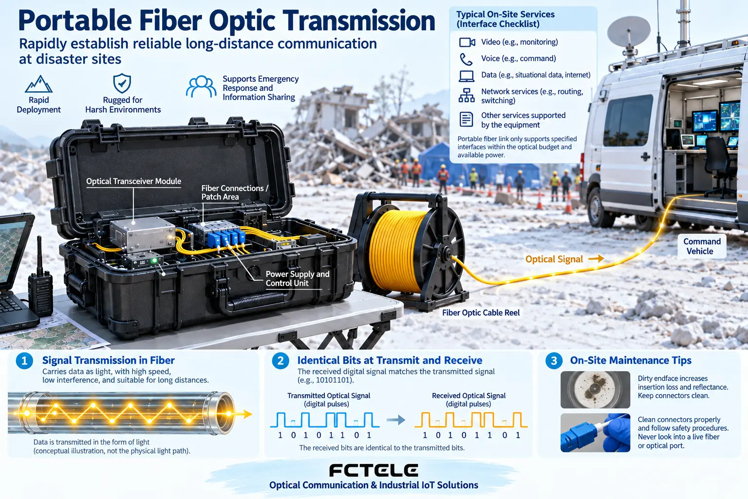
Portable power supply depends on input and continuous operation
Batteries, power adapters, or vehicle power must meet the device’s input voltage, polarity, power, and wiring requirements. Battery capacity cannot be directly equated with operating time: you also need to consider conversion losses, load changes, and temperature effects. Establish clear power switching and recovery procedures to avoid repeated device restarts caused by voltage drops. Backup power supplies, connectors, and consumables should also be included in the plan, not just spare fiber cable.
Fiber cable deployment fears end-face contamination and mechanical damage most
Protect connector end faces, route cables according to the allowed bend radius, and avoid wheel crushing, sharp edges, and pull points. Cleaning and inspection should use methods suitable for the connector. Do not touch the end face with your hands, and do not look directly into a glowing optical port. Keep proper tension when paying out and recovering cable from the reel, and leave maintenance space when securing excess cable. A so-called ruggedized housing does not automatically prove water, dust, drop, or temperature ratings; you should check the specific verified conditions.
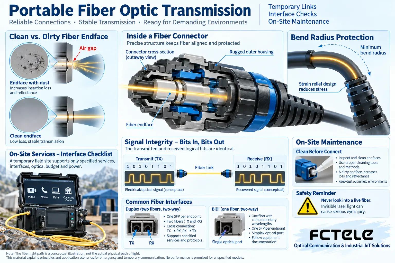
Acceptance records are the basis for fast recovery next time
Record the models at both ends, interface configuration, core numbers, power readings, power supply status, and service test results. Test each interface first, then test parallel services and power-off recovery. When a fault is found, change only one factor at a time. For optical path abnormalities, check connectors and loss; for service abnormalities, check protocols, configuration, and terminals, and distinguish equipment problems from temporary environmental problems. Putting together a short-fiber baseline and a spare parts list has more diagnostic value than just noting “it worked yesterday.”
Example: an emergency monitoring point connects to a temporary duty station
First confirm whether the monitoring point provides IP data or a dedicated serial port, how the software at the duty station receives it, and then set up matching devices at both ends. Before departure, save the short-fiber pair test results, configuration files, and spare parts list. On site, lay the fiber cable along a safe path, and label the connectors and core numbers. After cabling is complete, first verify power and the optical link, then verify the real service; during recovery, protect the end faces, check the fiber cable for damage, and update the records. The fact that one box of equipment can transmit images does not mean the interfaces of another scenario can be directly applied. A temporary network still needs agreed addresses and access boundaries with the existing network.
Translated from the Chinese technical article. Source first published: 2020-03-11. Source last revised: 2026-10-13T22:21:36+08:00. Read the Chinese source
