


On many fiber media converters, FX identifies the fiber-side interface or an associated state. Those two letters alone do not establish speed, wavelength, fiber type or LED meaning. They are not interchangeable with the complete standard name 100BASE-FX. Read the equipment specifications, understand how electrical signals pass through transmission, fiber and reception, and then verify the link and application separately. This avoids confusing a connector that fits, the presence of light and successful communication.
1. Separate three easily confused names
On an equipment panel, FX commonly identifies the fiber side; TX or TP sometimes labels the copper Ethernet port. In another context, TX on an optical module means transmit and RX means receive. The same TX abbreviation can therefore describe different objects in different positions. Check whether it appears beside an RJ45 port or an optical interface, and consult the manual’s port diagram. Do not apply another device’s markings indiscriminately.
100BASE-FX names a particular Fast Ethernet optical interface, rather than all optical ports. An example in official module documentation uses multimode fiber at approximately 1300 nanometers; it does not support the claim that all FX interfaces use 850 nanometers. Conversely, a Gigabit converter retaining FX as a fiber-port abbreviation does not thereby become a Fast Ethernet device. The standard name identifies the interface system, while the panel abbreviation helps locate a port. Verify product parameters independently.
SC and LC describe connector forms; SFP describes a pluggable module form factor. Neither guarantees speed or wavelength. Two connectors fitting together establishes only part of the mechanical match, not compatible encoding, optical operating windows or fiber. A matching electrical plug does not establish every appliance rating either. That analogy distinguishes shape from capability; it cannot replace specification checks.
2. How the converter behind an FX port works
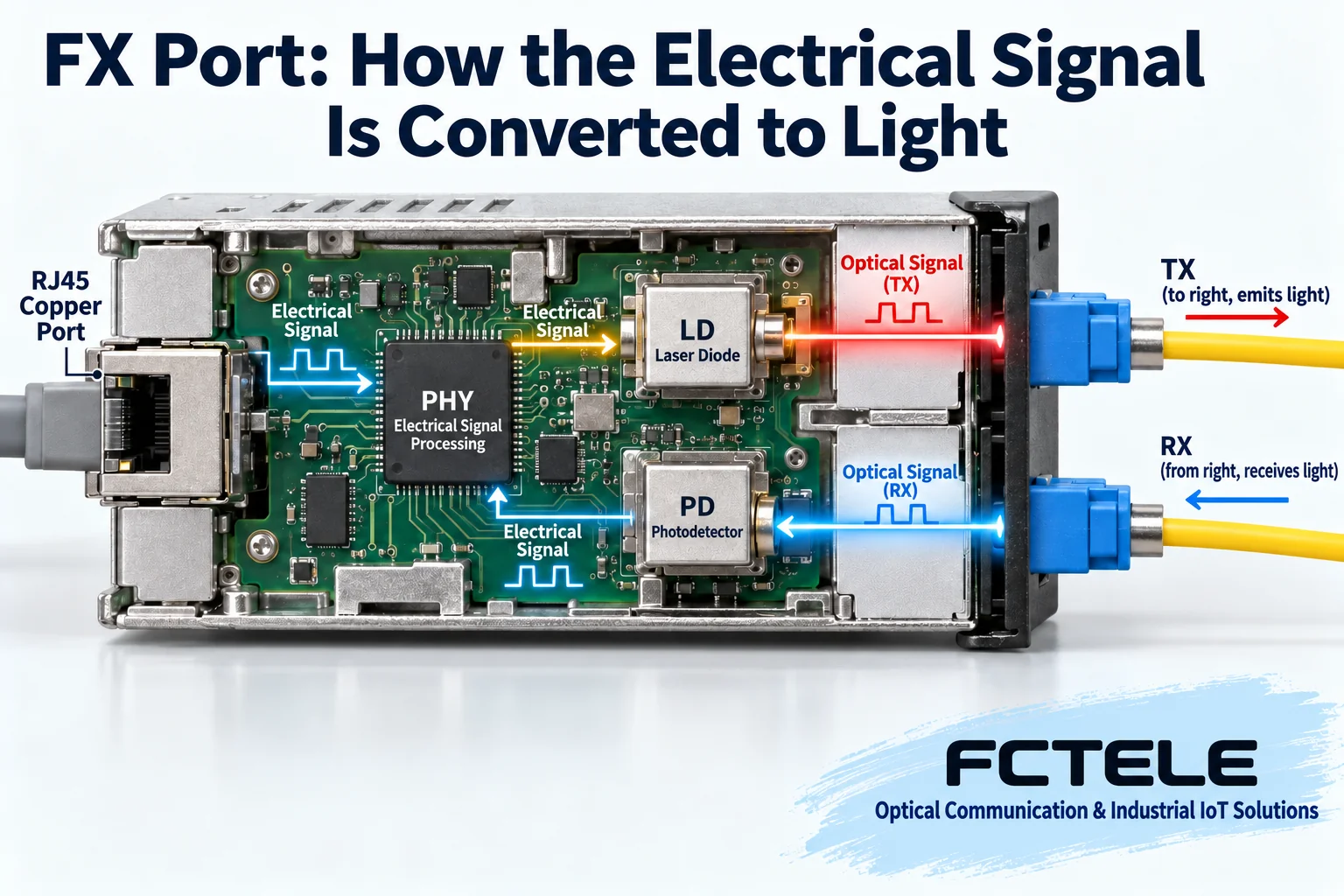
Consider an Ethernet converter with one optical and one copper port. Its RJ45 interface receives electrical network signals. Physical-layer circuitry processes the relevant encoding and timing, and the transmit path drives a laser whose optical output varies with the data. Light travels through the fiber core. A remote photodetector converts the received light into a very small current; amplification, decision circuitry and related processing recover a usable signal for the Ethernet interface. The link carries signals encoded according to its interface rules, rather than a video picture floating through glass.
Both ends of an ordinary network converter link can transmit and receive. A duplex-fiber link uses separate cores for opposite directions: local TX must reach remote RX, and the reverse path follows the opposite correspondence. Single-fiber BiDi distinguishes the directions by wavelength, with complementary transmit and receive conditions at the endpoints. A/B commonly identifies the pairing relationship, rather than one transmit-only box and one receive-only box. Ordinary bidirectional Ethernet needs both paths.
3. Why light alone may not establish a link
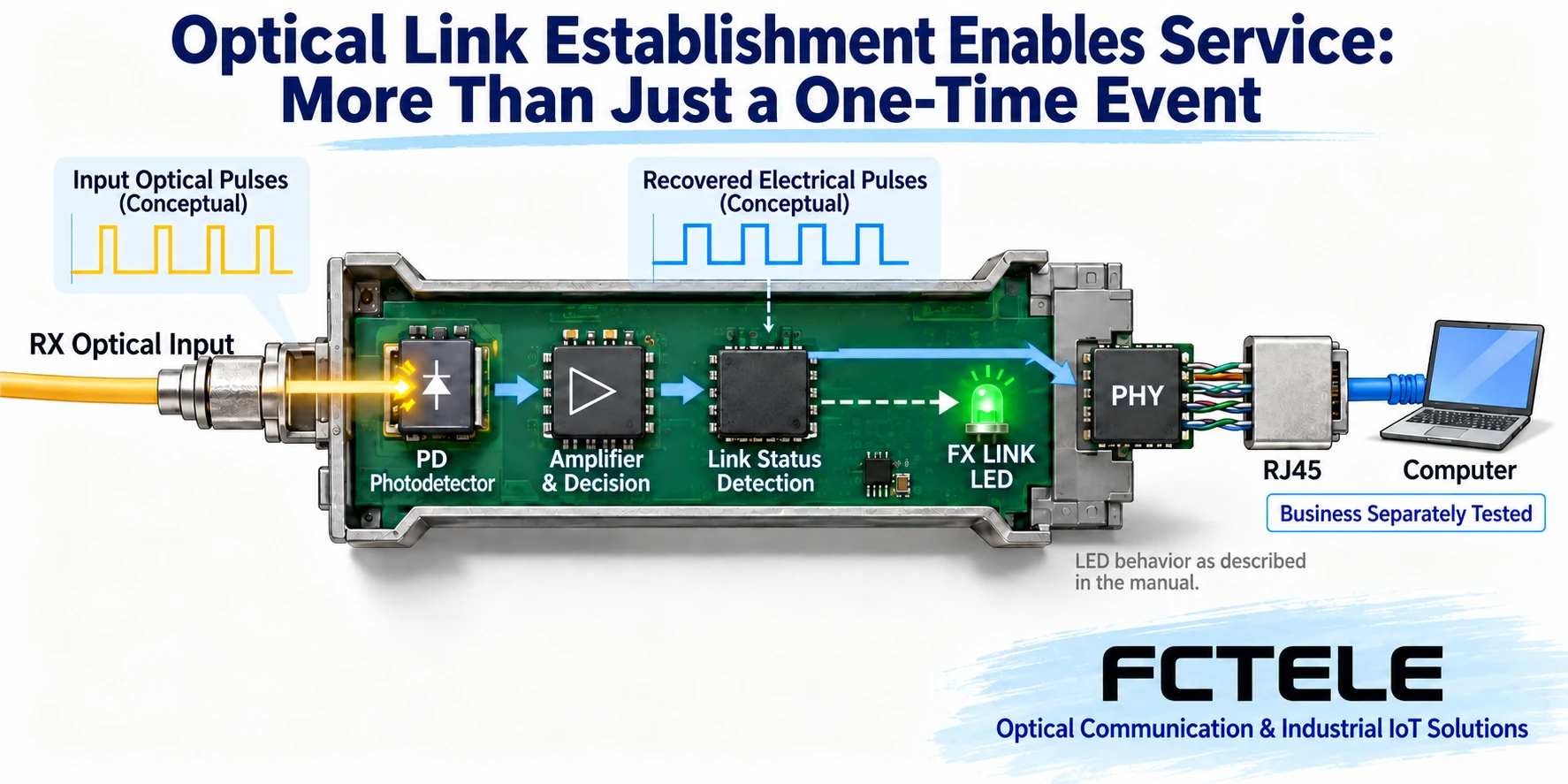
A receiver needs more than light: the signal must meet the interface’s speed, encoding and optical requirements. A power meter detecting energy establishes optical power at that measurement point, not successful data recognition. Equally, an unlit LED does not justify deciding by eye that the transmitter emits no light. Many communication wavelengths are invisible, and looking into an optical port is both unreliable and hazardous.
Received power has an allowable window. Too little makes reliable decisions difficult; too much can exceed the receiver’s upper limit. Rated distance is only one selection condition. Connectors, splices and bends affect loss. A long-reach module is not necessarily more suitable for a short jumper; check overload limits first. Optical power in dBm and link loss in dB are different quantities. Do not treat a loss value as a received-power reading.
Keep two complementary records for the actual link. One lists both devices and modules, full model numbers, interface speed, fiber type, transmit wavelength and receive range. The other traces local transmission to remote reception. For duplex fiber, record core numbers and ports; for single fiber, record complementary wavelengths. Descriptions such as both rated for twenty kilometers or both having blue connectors cannot establish compatibility.
4. What an FX LED actually proves
LEDs usually follow internal device-state logic; they are not miniature optical power meters. FX, LINK and ACT may distinguish link and activity or combine them in one indicator. A steady LED meaning link-up and a flashing LED meaning traffic on one model does not establish a universal rule. Read the manual and inspect power, optical ports, copper ports and the actual application at both ends. Flashing does not universally mean instability.
A visibly dimmer LED does not directly establish increasing fiber loss. Viewing angle, ambient light, LED drive and aging can all change its appearance. To check received power, use diagnostics that the actual module and host support or an appropriate instrument. Do not invent management-interface power readings for equipment lacking that capability.
5. Apply abbreviations to documented equipment
FCTEL B-series one-optical/one-copper Gigabit product documentation lists single-mode single-fiber, single-mode duplex-fiber and multimode duplex-fiber options. These are different ordering configurations, not modes every unit can acquire by moving a switch. Copper auto-negotiation or automatic crossover does not imply that the optical port accepts arbitrary speeds or corrects reversed optical TX/RX. Specify the version and compare the delivered label with that version’s manual.
For remote status diagnosis, separate documentation for FCTEL remotely managed one-optical/one-copper products describes OAM management, cooperation with the corresponding central managed equipment, LFP and power-loss detection. These features can distinguish fault layers, but require confirmation of the actual pairing and settings. They are not universal on ordinary converters. Corroborate managed status with field measurements rather than treating an alarm name as the final cause.
6. Move from an illuminated LED to application acceptance
Suppose a camera uploads video through a converter pair. Acceptance must do more than inspect the control-room FX LED. Confirm power and port parameters at both ends, then traffic in both directions. Next check camera addressing, subnet settings, switch VLANs and application access. A picture appearing once establishes that some traffic passed at that moment; it does not prove continuous-load reliability or successful remote-control requests. Save results under the project’s required duration and application conditions.
Keep full model numbers, normal LED states, fiber routes, received power at both ends and a configuration baseline. Future dark LEDs, intermittent outages or application failures can then be compared with changes in optics, restarts or network configuration. Schedule fiber removal, module replacement and power interruption within an authorized maintenance window. Restore dust protection, labels and patching afterward. Understanding FX helps locate the correct fault layer, rather than memorize a universal set of LED colors.
Translated from the Chinese technical article. Source first published: 2023-11-03. Source last revised: 2026-10-13T15:15:28+08:00. Read the Chinese source
