


A gigabit fiber transceiver connects to fiber in the middle, and usually still connects to network cables on both sides, so its cabling quality cannot be judged by the optical cable alone. Think of the whole route as several continuous road sections: on the electrical port side, high-speed electrical signals must pass correctly through four pairs of twisted pair; on the optical port side, the optical parameters at both ends must match and the received light must have a suitable strength. If any section fails, the service may become slow or unstable. The following starts with why twisted pair is twisted, how loss and crosstalk occur, and then explains copper cable and fiber acceptance separately.
Treat the electrical port and optical port as two channels
A transceiver will not hide problems on the electrical port, and it will not make the optical port rate automatically equal the number shown on the electrical port. First check what rates and negotiation methods the electrical port supports, then check the fixed or available modes of the optical port. Being able to establish a link between devices means each side meets the corresponding transmission requirements; it does not mean fiber has universal compatibility. The complete path also includes computer patch cords, patch panels, the transceiver electrical port, optical modules or fixed optical ports, optical patch cords and intermediate splices; if one section is missed, it is easy to blame the whole service problem on the last visible cable.
A transceiver connects an Ethernet electrical port and a compatible optical port, and the two media each have their own limits. Negotiating the electrical port to gigabit does not guarantee that the optical port also works at the same rate; some devices have a fixed optical port rate or a specific negotiation mode, so the product documentation should be checked. Structured cabling also includes patch cords, patch panels and connectors, and testing only one roll of cable is not enough. First draw the complete path and mark each section’s medium, length, connectors and device ports, so later budgeting and testing will not miss intermediate links.
Copper channels depend on four pairs and their supporting connections
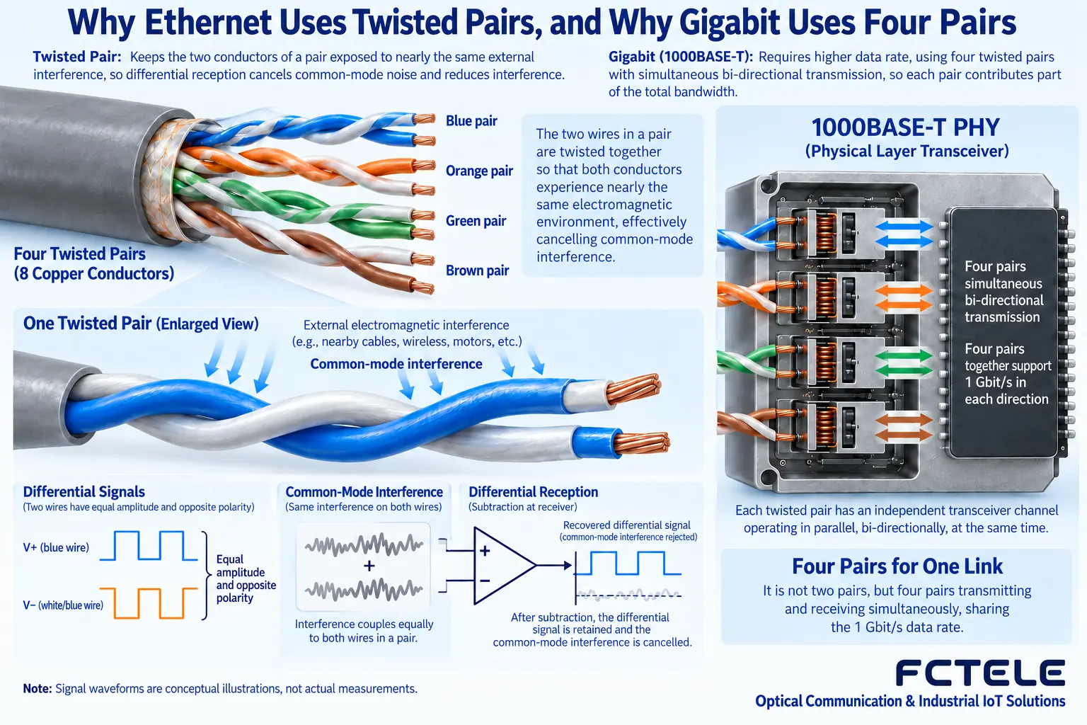
Figure 1 shows one pair of conductors in twisted pair. The receiver mainly compares the difference between the two wires; if external interference affects them at approximately the same time, the common part can be suppressed in the differential comparison. Twisting the conductors helps make the coupling conditions along the line more balanced, and it also affects the interaction between wire pairs, but it cannot make all interference disappear. 1000BASE-T uses four pairs, and every pair participates in transmission; it is not a case of leaving four wires idle. Untwisting a long twist length, crushing the cable or making poor connectors may affect performance, even if a wiremap tester can still show that every wire is continuous.
Common 1000BASE-T uses four pairs of twisted pair, and copper channels of Category 5e or higher that meet the corresponding requirements can be used for this type of application. Common standard channels are designed for a 100-meter range, but the combination of patch cords and connectors must be considered, and permanent link and full channel length must not be confused. Installation must not connect only two pairs, and must not untwist too much or squeeze the cable excessively. Modules, patch cords and patch panels must match, to avoid a higher-category cable paired with unsuitable connectors ending up with only a nice-looking label.
Continuity testing and performance certification are different
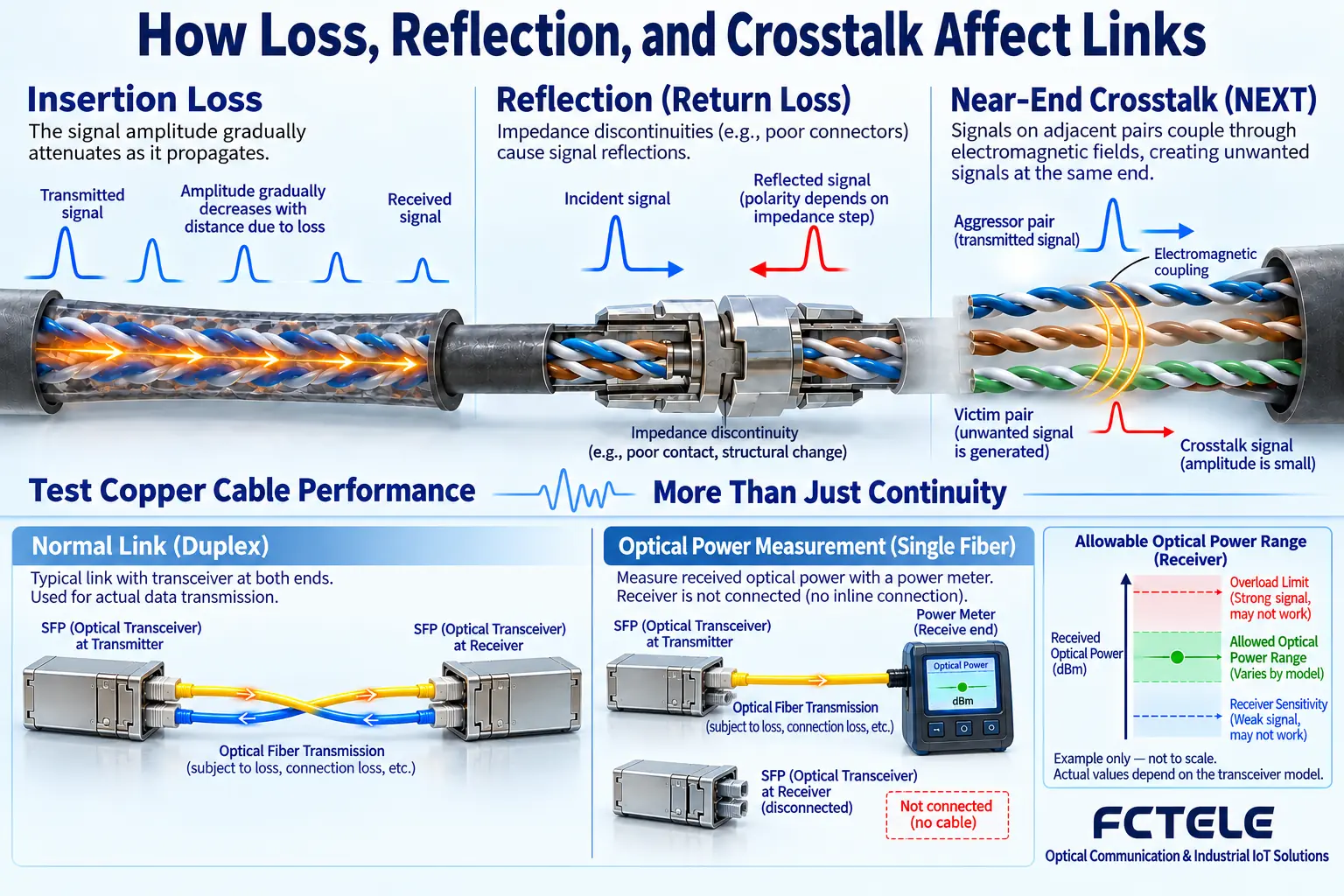
Figure 2 separates three problems. Insertion loss means the signal weakens as it travels along the path to the other end; return loss is related to impedance discontinuity, where part of the signal reflects back; crosstalk is when activity on one wire pair couples into another wire pair. They cannot be distinguished by simply saying ‘the network cable is bad.’ A wiremap tester is suitable for finding basic connection errors, while a performance tester must also measure the corresponding high-frequency indicators and use the correct limits. MHz describes a frequency range, Gb/s describes a data rate, and modulation and encoding lie in between, so one number cannot be directly converted into the other.
A simple wiremap tester can find broken wires, short circuits and some wiring errors, but it cannot fully evaluate insertion loss, return loss and crosstalk. Formal acceptance should use an appropriate tester and the corresponding test limits, and record whether a permanent link or a channel was tested. Relying on ping or a speed test only shows the service performance at that moment and cannot replace cabling certification. The frequency unit MHz and the Ethernet rate Gb/s are different quantities; cable frequency should not be directly multiplied into a data rate, or a theoretical capacity formula alone should not be used to decide whether field cable is qualified.
Fiber type follows the optical port specification
On the fiber side, too, it cannot be fixedly said that ‘single-mode can all reach some distance and multimode can all reach some distance.’ The optical standard, fiber core conditions, wavelength and transceiver parameters together determine the applicable range, and connectors and splices add more loss. Dual fiber must ensure that transmit goes to the opposite receiver, and single fiber must use complementary wavelengths; the endface type must also be consistent. If there is already optical cable on site, first check the type and test records, then choose matching equipment; this is more reliable than first buying the longest-distance module. Whether two nominally gigabit products interoperate still requires checking the corresponding optical port and Ethernet rules.
Check the single-mode/multimode support, wavelength, interface, fiber core count and rate of the optical module or fixed optical port. Multimode cannot be fixedly said to run a certain universal number of kilometers; the actual distance is related to the optical standard, fiber core conditions and link loss. For single-fiber bidirectional, check complementary wavelengths; for dual fiber, check TX/RX crossover; for connectors, also confirm the endface type and do not mix them directly by color. Existing optical cable can first be tested and its records checked, then the optical port to use can be decided, avoiding buying equipment and then finding that the fiber core does not match.
The loss budget must prevent both weak light and overload
The power budget is used to answer ‘is the light reaching the receiver within the usable range,’ not just to ask whether it is bright enough. The right side of Figure 2 shows the window between sensitivity and the overload upper limit; the actual values are specified by the equipment. Too weak makes judgment difficult, and too strong may also cause overload. The calculation should cover the worst-case transmit, connection and receive conditions, and leave maintenance margin. A short fiber helps eliminate path complexity, but power still must be checked; it cannot be estimated by eye, and the amount of attenuation to add cannot be decided out of thin air based on the number of kilometers. Test tools and methods must match the optical wavelength and equipment.
Include optical cable attenuation, splices, connectors and maintenance margin in the budget, confirm that receive sensitivity is still met under worst-case conditions, and at the same time check whether the maximum receive power of a short link exceeds the limit. For selection, refer to the test conditions specified for the module, and do not simply convert remaining power based on the nominal transmission distance. Cleaning endfaces, reasonable bending and path labeling all affect long-term maintenance. Fiber does not carry the conductor connection between the two ends, but local power and copper cable surge and grounding still need to be handled independently.
Example: gigabit uplink renovation between buildings
If the site only negotiates to 100 Mbps, first check the port capabilities at both ends, the integrity of the four pairs and the negotiation settings, then perform a copper cable performance check; if the optical port repeatedly flaps, locate the issue along power, endface, core number and module compatibility. Unsatisfactory service throughput may also involve terminal, uplink or protocol factors, and fiber quality cannot be asserted just from a speed test. When changing cables, change one variable at a time, and save error counters and load conditions. Final delivery should include copper cable test reports, optical link loss and power, a port table and actual service results, so future expansion also has a basis.
First organize the complete path of the copper cable at both ends and the optical cable between buildings, perform the corresponding performance test on the copper cable, measure insertion loss on the optical link and check the endfaces. Use matching transceivers or switch optical ports, verify the rate, sustained actual traffic and error counters, then perform a power-off recovery test. If it only negotiates to 100 Mbps, first check the four pairs and port capabilities; if the optical port flaps, check power and connectors, and do not blindly replace it with a longer-distance module. Save test reports, core numbers, module parameters and the port table to provide a basis for later expansion.
FAQ: Does a higher-category network cable always make the system faster?
Not necessarily. More suitable cabling may provide better conditions or upgrade space, but the existing device ports, uplink and service capabilities are still limits. Cable, patch cords, connectors and installation must form a complete channel that meets the requirements; choosing one roll of higher-category cable alone cannot guarantee the result. The fiber side also follows the complete-link principle. The selection conclusion should come from the corresponding standards, equipment documentation and on-site testing, not from a category label or network cable continuity alone.
Translated from the Chinese technical article. Source first published: 2019-08-19. Source last revised: 2026-10-13T22:50:44+08:00. Read the Chinese source
