


First ask who the bypass is bypassing, not first promise seamlessness
Bypass means to go around, that is, to let a signal bypass a processing step it originally went through. It may be used for optical path pass-through after an industrial switch loses power, or it may be used to bypass an inline security inspection tool in the network. The two protect different objects and organize interfaces differently. You cannot, just because they share the same English name, treat them as a backup switch that automatically takes over all failures.
Suppose an optical link passes through multiple field cabinets, and one cabinet loses power. The engineering goal may be to let upstream still communicate with downstream. Another scenario is inserting an inspection device between two network zones, and when the inspection device fails, you want another path. First write clearly which device is being bypassed and which services should still be available, then choose the bypass architecture, so you can judge whether it solves the actual problem.
Bypass does not guarantee that the function of the bypassed device continues to run. Local terminals on an industrial node may lose access, and the inspection by a security tool may be skipped. Even if the main path later recovers, you still need to check device startup, link establishment, and service status. Claims such as mission-critical or seamless in a title is not performance evidence. How long an interruption is allowed and what loss is allowed should be determined by business requirements and testing.
Industrial optical bypass: switches when powered, passes through when power is lost
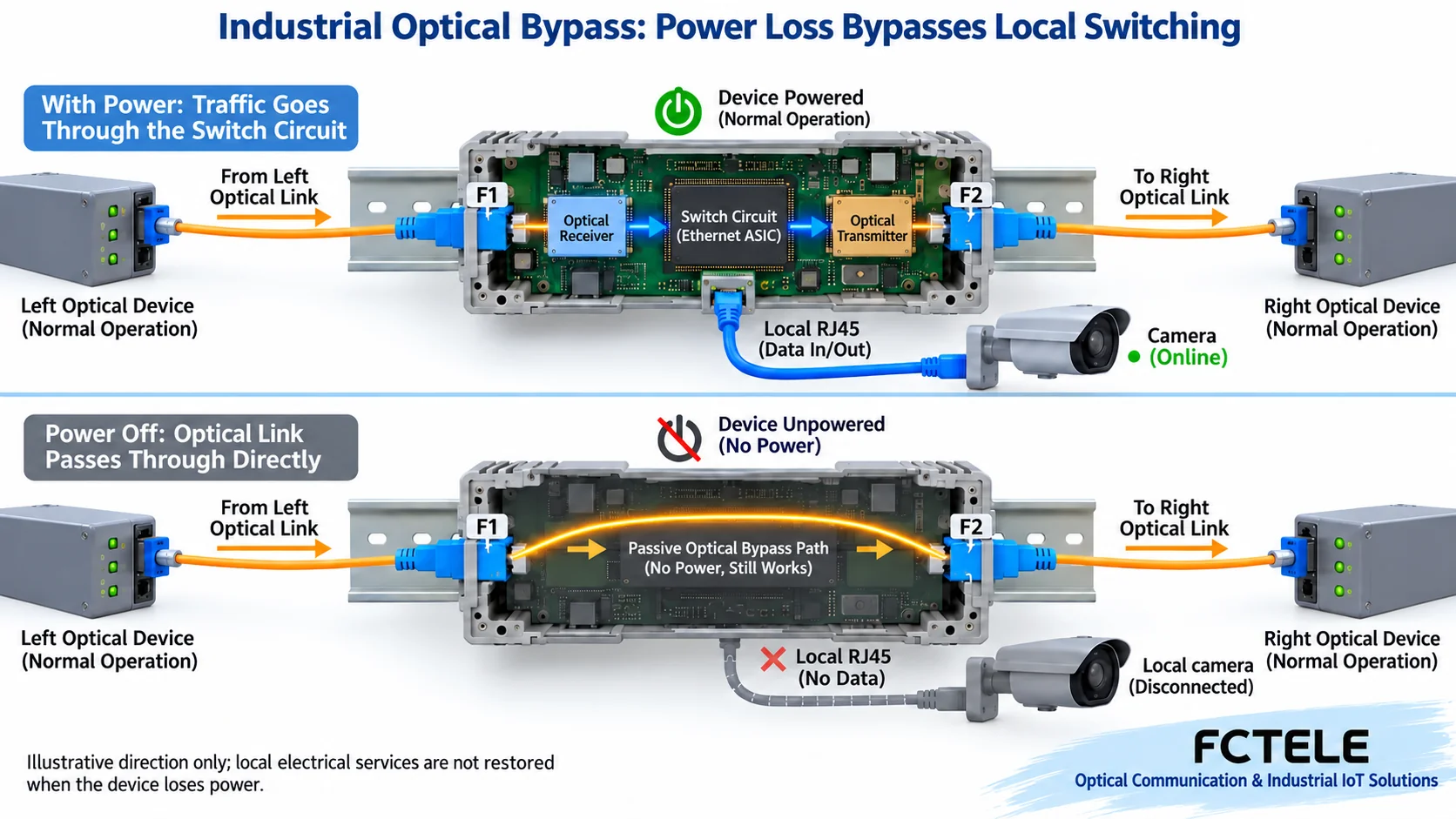
A device with this design, when powered, uses optical reception, switching circuits, and optical transmission to participate in network forwarding, and local electrical ports can also connect terminals. After power loss, the specified bypass optical interfaces connect according to the product design, so external optical signals bypass the switching part that lost power. This is a physical path change for specific ports and a specific state, not a case where turning off a software option gives an ordinary switch the same capability.
The Feichang Technology two-optical eight-electrical product detail 3307 clearly states that when the device loses power, the two Bypass interfaces F1 and F2 pass through, and when powered, the corresponding optical ports can serve as gigabit optical Ethernet switching interfaces. It provides the power-loss bypass condition that can be checked at procurement. You cannot further assume that a software crash, a single alarm, a broken fiber, or an application timeout will trigger the same action.
The normal path through local switching and the pass-through path after power loss are different. The diagram shows only one direction; confirm actual bidirectional wiring according to the delivery manual. Optical bypass does not supply power to local electrical ports or cameras, nor does it continue to execute VLAN, multicast, management, and port policies for a powered-off node. Redundant power supplies can help maintain power, but redundant power and bypass are two different functions.
After pass-through, recheck the optical path conditions
The two originally adjacent link segments may form a longer end-to-end optical path after bypass. You should check the actual fiber type, transmit and receive wavelengths, rate, connection method, and protocol compatibility at both ends. You cannot assume that just because F1 and F2 can accept connectors, it will necessarily work after bypass. The pairing method for different modules and single-fiber or dual-fiber versions must be confirmed according to the specific device documentation.
Optical budget can be understood as whether the optical power the transmitter can provide, after line and component losses, is still within the range allowed by the receiver. Bypass components, connectors, splices, and optical cables all affect loss. Which losses actually need to be added depends on the optical path of that model. Check for insufficient power and ensure it does not exceed the allowed upper limit of the receiver.
The optical path for one power-loss point and for multiple consecutive power-loss points may differ. Confirm separately the number of nodes allowed to be bypassed and the measurement conditions. The nominal transmission distance is not a guarantee for any number of bypass stages. At the planning stage, request insertion loss and port pairing data. At commissioning, measure the corresponding link in normal and bypass states, keep path and measurement records, and do not replace the budget with indicator lights.
Inline tool bypass: another design that bypasses a processing step
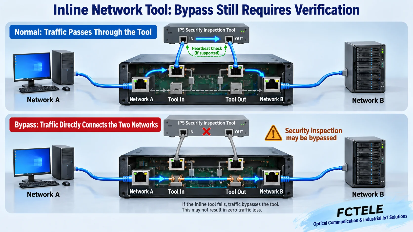
A security or inspection tool deployed inline sits on the mandatory service path. Normally, traffic enters the tool, is processed, and returns to the network. An external bypass device, when specified conditions are met, can directly connect the two sides of the network and bypass the tool. Here the network ports and tool ports play different roles. You cannot get the same control by casually connecting the tool to a mirror port.
Some inline bypass devices use heartbeat packets to detect whether the tool’s processing path can still return, rather than only checking whether the network cable is connected. Garland’s official description describes this method: the bypass device sends detection packets to the tool and checks the return, then decides the state according to configuration. This only explains that type of mechanism; do not write a third party’s heartbeat function as already supported by a Feichang Technology industrial optical bypass model.
Link status alone cannot prove that application processing is normal; a heartbeat return also does not necessarily prove that all services meet requirements. Detection content, period, timeout, and recovery conditions should be determined by model. The detection line in the diagram only represents the tool loop path; it does not mean detection packets are sent to all production terminals. The common idea of both bypass types is to bypass a specified step, but the specific trigger logic must be confirmed separately.
The connection continues, but security inspection may stop
After bypassing a security tool, some services may continue to reach the target, but the inspection or blocking performed by the original tool may no longer execute. This is not a simple judgment of a functional defect, but a working state that the solution must make clear: should the link continue communicating when it fails, or should it stop passing? This should be determined jointly by the system purpose, access boundary, and responsible personnel. You cannot replace all requirements with a single connectivity rate metric.
A failure policy that continues passing is often called fail-open, and a policy that stops passing is often called fail-closed. The specific meaning should be understood in relation to network equipment, not building door locks. What state a device is in after losing power, and whether restoring power immediately puts the tool back inline, both require documentation and testing. Do not assume all bypass products have two modes, and even less should you treat industrial power-loss optical pass-through as having completed the security policy design.
The maintenance plan should let duty personnel know when the system is in bypass state, which functions are missing, and who restores it. If there are alarms, logs, or status outputs, configure and verify them according to model. If there is no such function, you cannot write in the solution that all personnel will be automatically notified. If a backup inspection device is needed, list the takeover path and state synchronization conditions separately.
Accept bypass, ring protection, and device redundancy separately
Optical bypass bypasses a local node, while ring mechanisms usually respond to link changes by changing the topology allowed to forward, and device redundancy also involves another device taking over. They can be combined in a complete design, but they cannot replace each other. A broken fiber will not be reconnected just because a switch chip is bypassed, and an upstream power interruption is not necessarily within the scope that this node’s bypass can protect.
The Feichang Technology 3307 detail lists STP/RSTP features. When using a ring topology, you need to confirm the protocol and configuration of all nodes, and observe how the network re-establishes links and converges after power-loss bypass changes the optical path. You cannot add the two names built-in bypass and RSTP together and claim that any failure is uninterrupted or has some unknown recovery time.
Bypass action, interface re-establishment, topology change, and application re-communication are different stages. Engineering records should separately note the time and result of each, especially checking the change again after power is restored. Some services can retry on their own, while some control tasks have strict time limits. One Ping recovery only proves one connectivity observation; it does not prove that all application states remain consistent.
Use clear failure scenarios for delivery testing
Before testing, save the normal configuration and port mapping, and list the failures planned for verification: local node power loss, upstream link break, tool processing abnormality, or power restoration. Only scenarios explicitly supported by the device and needed by the project should be included in the corresponding acceptance. When a running system is involved, arrange a maintenance window and recovery steps, establish a baseline in an isolated environment first, and do not replace a test plan with random fiber unplugging.
Under a stable service load, record consecutive packet sequence numbers, loss count, latency changes, link status, and actual application response. First verify the normal path, then verify the specified bypass path, and finally verify recovery. For optical bypass, also measure the corresponding received optical conditions; for inline tool bypass, check whether processing is truly bypassed and whether detection triggering matches the agreement, avoiding observing only one status light.
Acceptance should not test only one direction from upstream to downstream; check the return path as required by the service. Whether local electrical port terminals lose connection should also be clearly recorded. If seamlessness is required, write clearly the allowed loss, observation time resolution, load, number of tests, and success criteria, and support conclusions with results, rather than equating no observed flicker with no loss.
Make the bypass state understandable to the next maintenance person
The delivery should retain device and module information at both ends, normal and bypass path diagrams, trigger and recovery conditions, optical measurement records, test load, and abnormal logs. If the product model column is not clearly marked, confirm the version from the order documents and device nameplate; do not infer all configurations from a webpage title. After expansion or module replacement, recheck the optical budget and adjacency relationships after bypass.
The value of Bypass is that under clear failure conditions it provides another verified path for a specified step. First confirm who is bypassed, then check the remaining path and the lost functions, and finally verify failure and recovery. Only then can bypass change from a vague reliability term into a design that can be executed and maintained on site.
Documentation note: The principle diagrams have been checked for technical content and are used to explain general mechanisms. They are not product photos or measured records. Specific interfaces, modes, and capabilities are subject to the selected model, version, and on-site verification.
Verification materials:Feichang Technology Bypass industrial switch category
Feichang Technology two-optical eight-electrical switch with optical bypass detail
Garland inline bypass and heartbeat detection description
Garland description of the mode that stops passing on failure
Industrial switch redundancy principles and acceptance
Translated from the Chinese technical article. Source first published: 2024-08-30. Source last revised: 2026-10-13T14:07:46+08:00. Read the Chinese source
