


An Ethernet fiber transceiver adapts the Ethernet signal on the copper cable side to the fiber side, and then a compatible remote end restores the electrical signal. What it extends is a matched Ethernet link; it does not automatically replace a router, a PON optical modem, or every protocol converter. Before use, first understand the signal path, then check both ends, the fiber core, and the power conditions, so you can avoid judging success only by whether the link light turns on after plugging it in.
The data does not turn into a glowing picture
A camera, computer, or other Ethernet device encapsulates data into frames, and then the physical interface encodes them into line signals. The transceiver receives these signals on the copper side, and after internal adaptation drives the optical transmitter, so that the state of the light carries the encoded information. The fiber transmits the light to the far end, the detector converts the light into current, and the following circuits recover the data and send it to the copper interface. Internally there may be buffering or switching processing, so not every model should be treated as a completely delay-free wire. A picture is only one kind of data content; what the optical path actually transmits is a signal. Understanding it this way prevents the mistaken idea that an ordinary Ethernet fiber media converter can directly connect to analog video BNC or any serial port.
Why replace copper cable with fiber
Copper cable signals are affected during propagation by factors such as attenuation, crosstalk, and reflection, and each Ethernet physical standard has corresponding cabling requirements. Fiber uses a different medium and, under suitable module and link conditions, can support different distances or application arrangements. Fiber does not have the same conductive path across segments as copper data lines, and it is also suitable for certain electromagnetic environments, but local power supplies, metal components, and other connections still need protection. Fiber cannot be understood as making all electrical risks disappear. Single-mode and multimode describe optical propagation modes; the actual usable distance is also determined by rate, wavelength, transmit and receive capabilities, so you cannot memorize one fixed answer like “single-mode is always how many kilometers, multimode is always how many kilometers.”
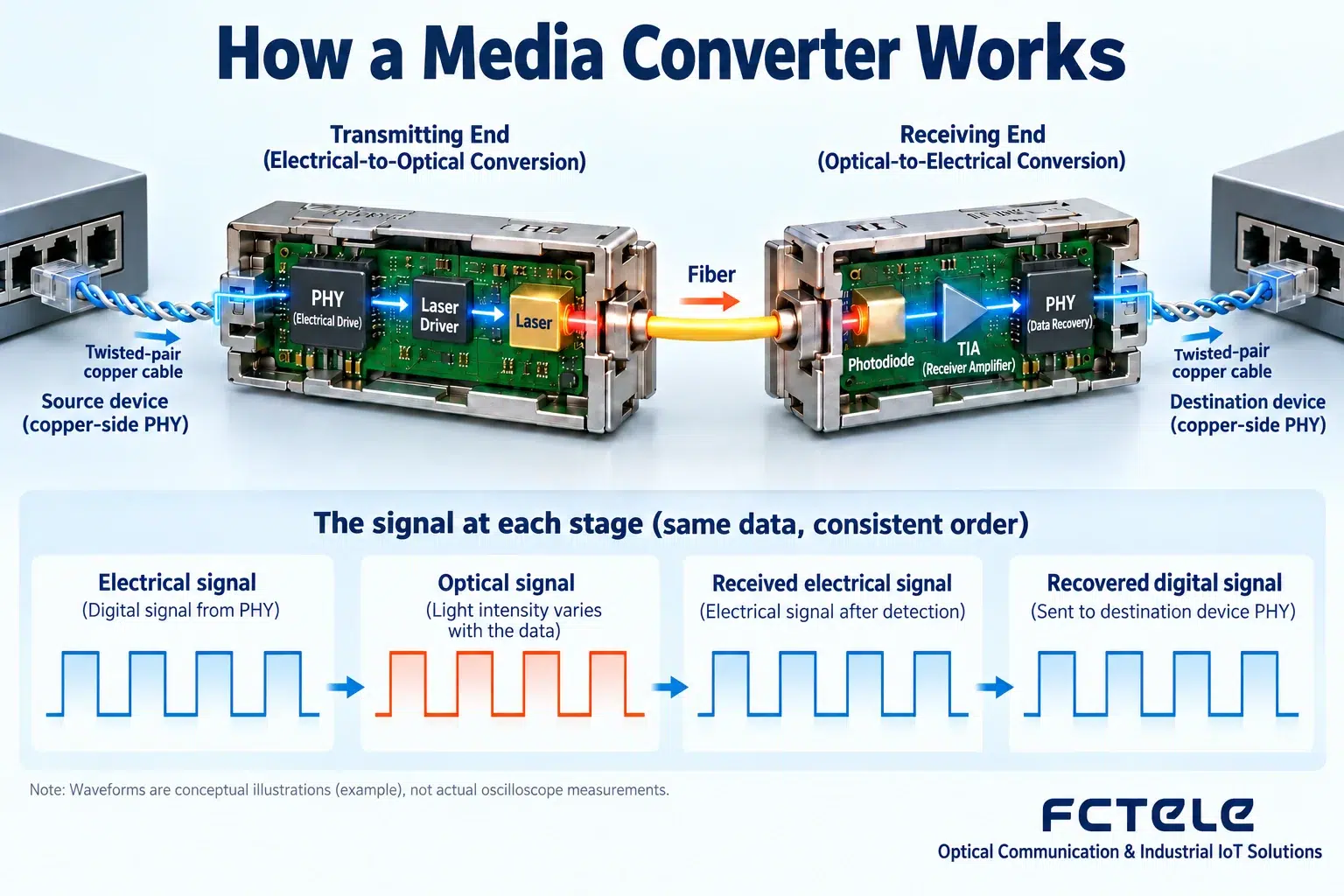
The core of dual-fiber connection is transmit to receive
TX means transmit, and RX means receive. In a common dual-fiber system, one fiber core carries A to B, and the other carries B to A, so the local TX should connect to the remote RX, and the same applies in the opposite direction. Each direction needs a complete path, and you cannot declare bidirectional operation normal after testing only one fiber. Jumper labels, patch panel order, and intermediate splices can all change the actual fiber core correspondence, so they need to be checked by number. Swapping the two fibers can sometimes correct a direction error, but it cannot solve rate, wavelength, or device incompatibility. You also should not repeatedly unplug and plug a production link just to try your luck; first draw the connection clearly and make one clear change under maintenance conditions.
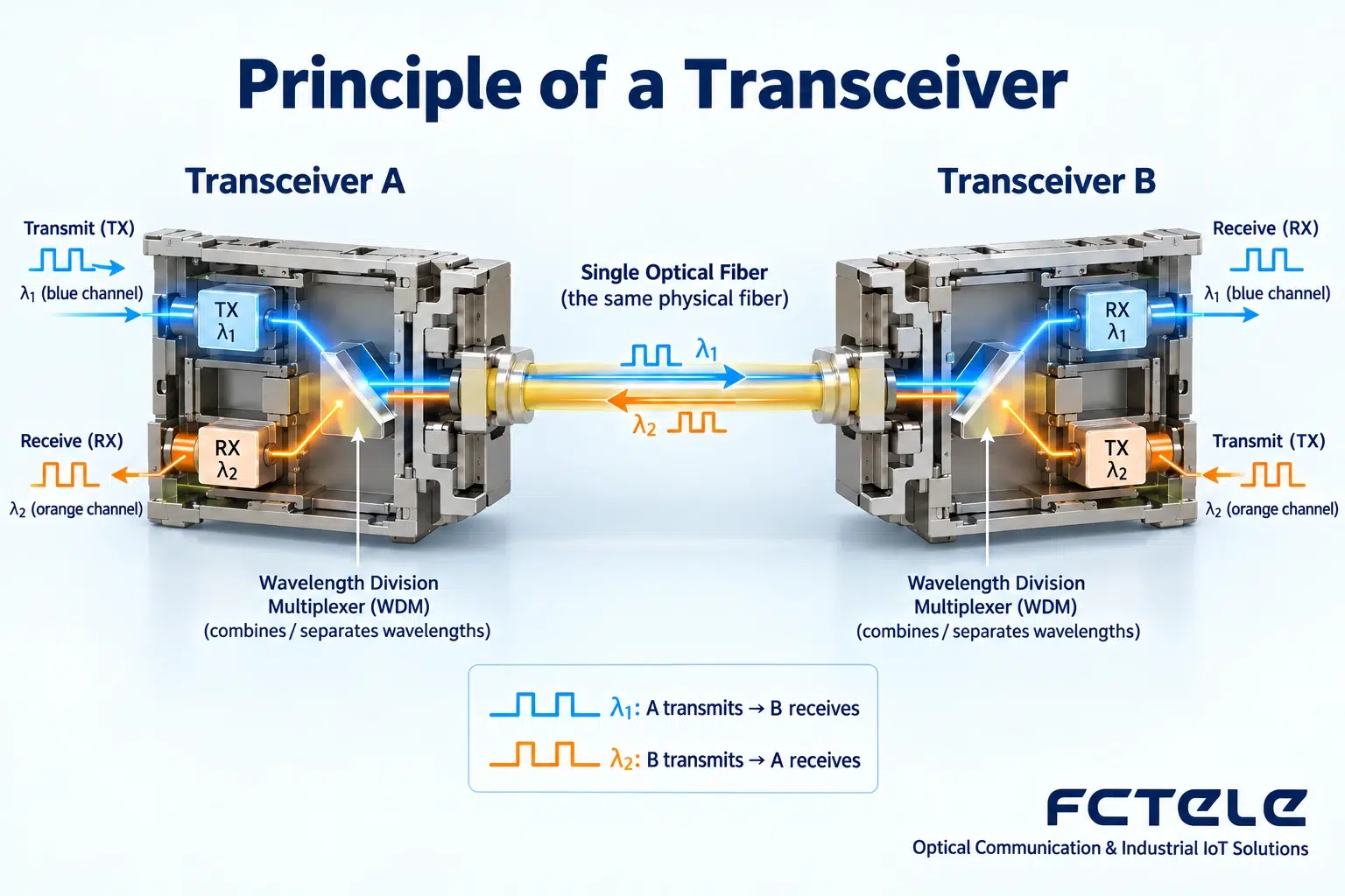
How single-fiber bidirectional transmission shares one fiber core
Single-fiber bidirectional transmission usually uses different wavelengths for the two directions and distinguishes them through internal optical filtering or separation components. The wavelength sent by A must be the wavelength B can receive, and the wavelength sent by B must be receivable by A. The two colors in the figure only symbolize two channels; communication light is often invisible, and it is not that there are really two colored roads inside the fiber core. Buying only two modules with the same name may result in buying the same side, causing pairing failure. In addition to wavelength, you also need to check rate, fiber, and power range. Single fiber saves physical fiber cores, but it does not mean a remote receiver is unnecessary, and it does not mean one port can connect to any number of ordinary transceivers.
Two transceivers are not the only legal combination
Transceivers are often used in pairs, but the remote end may also be a switch or other Ethernet device with a compatible optical port. The key is the physical rules of the optical interface and service matching, not that both enclosures must bear the same product name. The optical module form factor, connector, and nominal rate are only part of the conditions; you also need to confirm the specific standard, wavelength, fiber core, and host support. An ordinary point-to-point Ethernet optical port cannot be connected to an operator’s PON passive optical split network just because it uses the same fiber. Network-layer addresses, VLANs, and gateways also need to remain consistent with the design. A transceiver providing a link does not mean it completes network configuration for the upper-layer application; this functional boundary should be stated first.
During installation, check power, cleaning, and optical budget together
Check power supply, grounding, and installation environment according to the model, use a suitable power supply, and do not apply the same voltage or temperature to all products. Optical connectors should be inspected and cleaned according to specifications, exposure should be minimized after removing dust caps, and do not look directly into optical ports. Transmit power minus link loss determines roughly how much light the receiving end gets, but device error and margin also need to be considered in practice. If the receiving end is too weak, decisions may be unstable; if too strong, it may overload, so brighter is not always better. Short jumper loopback testing must also be within the allowed power range, and you cannot blindly connect high-power long-distance modules directly. Unknown attenuator values or replacing modules without basis should not replace design calculations.
How to gradually accept a cross-building connection
Suppose a switch in Building A needs to connect to a terminal switch in Building B. First determine the actual fiber core and interface conditions, and use compatible devices to establish a repeatable short-link baseline. Then connect the formal optical path, record power, rate, port errors, and alarms at both ends, and then run the real service. Test both directions with multiple packet lengths and expected load to confirm that the link is stable under the originally planned environment. A link light only reflects the state defined by the device and cannot by itself guarantee no bit errors or application availability. If A to B is normal but B to A is abnormal, first separate the transmit, fiber core, and receive paths corresponding to the direction, rather than replacing all devices together and guessing the root cause.
Common misunderstandings and daily maintenance
Being able to plug in the electrical port does not mean it automatically supports all rates; the optical port being lit does not mean all data frames are correct; switching to a longer-distance product does not mean a short cable is more stable. Some devices have link fault pass-through, which reflects a remote optical-side fault to the local electrical side, but the function and configuration depend on the model. During maintenance, keep records of ports, fiber cores, models, power, and diagnostics, and change only controllable variables each time. If the network is down, also check VLANs, addresses, and applications, to avoid repeatedly testing only at the physical layer. Truly mastering how to use it means being able to explain at which step the signal changes medium, how each direction corresponds, and what each test actually proves, rather than only memorizing the order of plugging in cables.
Principle verification materials:Official material 1;Official material 2. The general mechanisms and examples in this article do not replace the corresponding model manuals.
Translated from the Chinese technical article. Source first published: 2019-07-18. Source last revised: 2026-10-13T22:50:44+08:00. Read the Chinese source
