


An optical module converts the electrical data signals inside a host device into optical signals, and also converts received light back into electrical data. To understand it, you need to look at three separate questions: how it emits and receives light inside, what kind of slot its physical package fits, and which speed and protocol it actually supports. Being able to plug it in does not mean it can definitely communicate, and an optical port lighting up does not mean the service has passed acceptance testing.
A small module contains two paths going in opposite directions
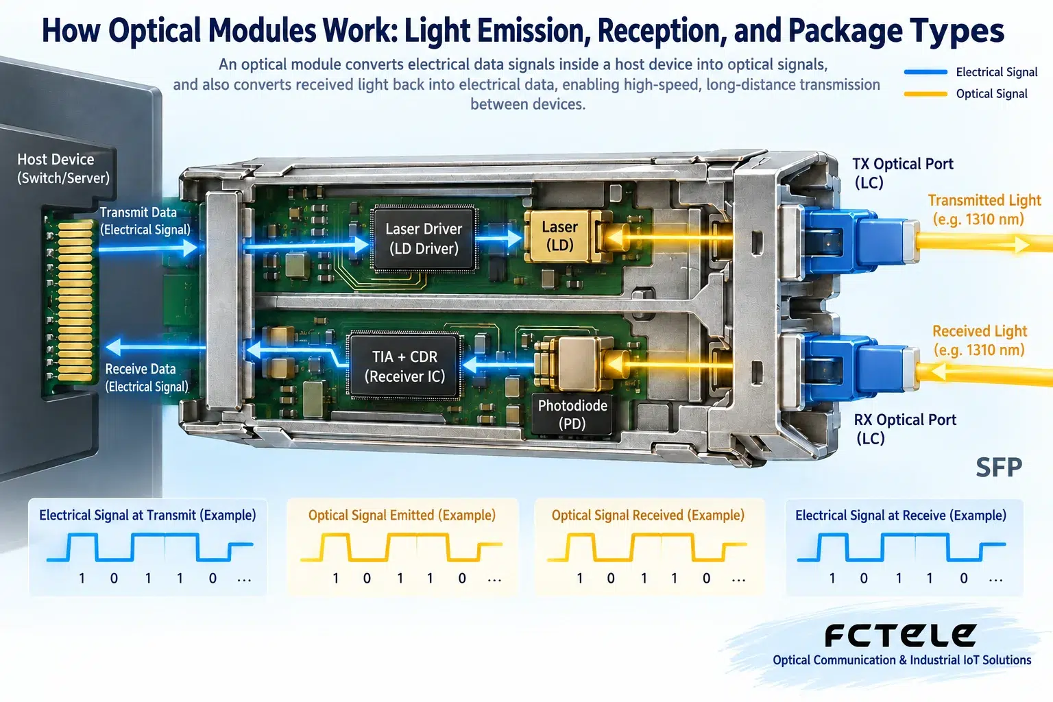
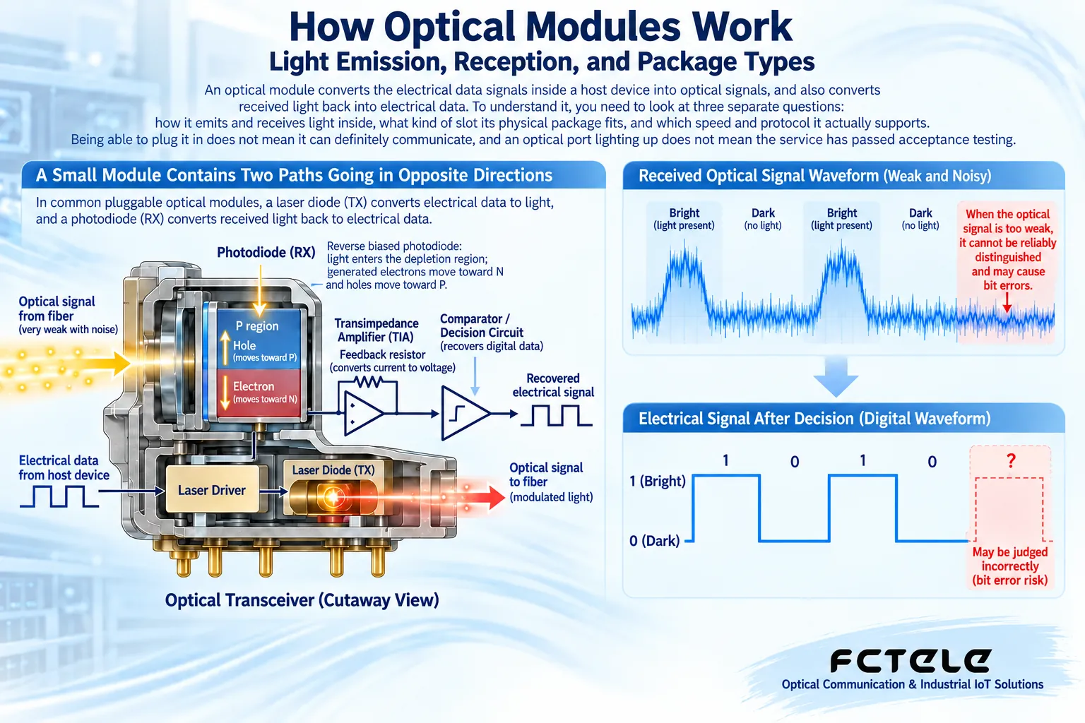
In common pluggable optical modules, the transmit direction starts from the electrical connection on the host side. The electrical signal passes through a transmit driver circuit, which controls the laser to emit light that changes with the data, and then the light enters the fiber through the optical interface. The receive direction starts when light from the fiber enters the module, where a photodetector converts the received light changes into a weak current, which then goes through amplification and other processing to provide an electrical signal to the host.
This is not light passing directly from one end of the module to the other. Electrical-to-optical conversion and optical-to-electrical conversion each happen inside the device, require power, and are affected by the device’s bandwidth, noise, and temperature. Dual-fiber modules usually separate transmit and receive into two optical ports; single-fiber bidirectional modules also need an internal wavelength separation structure so that both directions can share one fiber core.
Emitting light is not projecting a picture into the fiber
Ethernet equipment sends data encoded according to rules, not a continuous projection carrying a complete photo. The laser output changes with the electrical signal, and the receiving end recovers the corresponding electrical signal from the changes in light. The light pulses mentioned here are only a mechanism illustration to help understanding; the specific modulation, encoding, and signal shape vary by standard and implementation, so a teaching square wave cannot be treated as the measured waveform of all modules.
You can think of the transmitting end as a light blinking at an agreed rhythm, and the receiving end must know how to recognize that rhythm. If the two sides have different speeds or mismatched encoding methods, even if light is received, the data may not be correctly recognized. Increasing light brightness will not automatically change a 100 Mbps signal into a 1000 Mbps signal, and it certainly will not replace a protocol that the host does not originally support.
The transmit circuit also needs to output a suitable signal under specified operating conditions. The laser type, driving method, and thermal management affect performance, but readers do not need to memorize all device abbreviations first. When selecting, first confirm the standard, speed, wavelength, and optical budget; device details can serve as a basis for further verifying reliability and temperature conditions.
Why receiving light fears both too weak and too strong
The signal received by the photodetector is usually very small, and the receive circuit must amplify it and distinguish the data. When the signal is too weak, data changes can easily be drowned out by noise; when it is too strong, the receiver may also exceed its normal operating range. Receive sensitivity describes the requirement on the weak-signal side, while the receive overload limit defines the strong-signal side; both must be considered, and you cannot look only at the nominal transmission distance.
Optical power is commonly expressed in dBm, which is a logarithmic quantity relative to a fixed reference power. Line loss is usually expressed in dB, which represents a ratio before and after, not the same meaning. Subtracting line loss from transmit power to estimate the power reaching the receiver, and then comparing it with the receiver’s range, is the basic idea of an optical budget. Connectors, splice points, splitters, and reserved maintenance margin should all be included in the applicable model.
SFP and SFP+ are first of all package categories
Names such as SFP and SFP+ are related to the module’s physical form and host connection specification, and you cannot infer from the name alone that any protocol or any speed is supported. Common Gigabit Ethernet uses the corresponding SFP module, and common 10 Gigabit applications use the corresponding SFP+ module; whether lower speeds are compatible must be checked in both the host port and the module documentation, and it should not be written as a broad range such as “SFP covers from zero to ten Gigabit.”
The same form factor may also be used for different services, such as Ethernet and other transmission protocols. Some pluggable modules have an RJ45 copper port on the outside, not a fiber optic interface. Although they can be inserted into the corresponding slot, the line medium, power consumption, and heat dissipation requirements differ from those of optical modules. Therefore, observing that “the small metal boxes look the same” is not enough to complete selection.
How to separate single-mode, multimode, single-fiber, and dual-fiber
Single-mode and multimode describe the fiber propagation conditions, while single-fiber and dual-fiber describe how many fiber cores are used; the two sets of terms are not the same classification axis. Combinations such as single-mode single-fiber and single-mode dual-fiber may all exist. “Single-fiber” also does not mean communication can only be one-way; single-fiber bidirectional products can use two different wavelengths to carry the two directions separately.
When pairing single-fiber BiDi modules, you should read the complete transmit and receive wavelengths. For example, if one end transmits one wavelength and receives another wavelength, the opposite end needs a complementary configuration. Different products may use different wavelength combinations, and you cannot pair across series based only on the letters A-end and B-end. For dual-fiber, check whether one end’s transmit port is connected to the opposite end’s receive port; do not connect two transmit ports to each other.
Feichang Technology’s optical transmission and transceiver products include different optical port forms and specifications. For projects involving pluggable modules, the equipment ports and the ordered modules should be confirmed together. You cannot assume that all fixed optical port devices can have their modules replaced just because a certain series offers an SFP option, and you cannot extend one model’s distance, fiber type, and temperature specifications to the entire series.
What is most easily overlooked during installation is the end face and the host
Dust on the connector end face may block the effective optical path. Cleaning cannot rely on the naked eye judging that it “looks about the same”; applicable inspection and cleaning tools should be used, and inspection, cleaning, and re-inspection should be carried out according to on-site procedures. Do not look directly into an optical port or use your eyes to search for invisible laser light; unused interfaces should be properly protected from dust, and the cleaning status should still be checked before connection.
The host port is equally important: check the supported speed, module compatibility policy, power conditions, firmware, and alarm information. Digital diagnostic functions can provide some temperature, power supply, or optical power information, but whether they are available, what the readings mean, and their accuracy must be confirmed according to the module documentation. These data are supporting evidence and cannot replace service traffic testing and fault records.
A checking sequence that even a beginner can follow
First confirm the service to be transmitted and the target speed, then confirm what modules the host slot supports; next check the standards, wavelengths, fiber types, connectors, transmit and receive directions, and optical budget at both ends. Finally confirm power, temperature, and installation requirements, and label the modules and patch cords well. When equipment and line conditions allow, establish a baseline with a known-good short link, then extend it to the actual line.
If it does not work, check port status, optical power, module alarms, and error counters section by section; do not swap many parts at the same time, otherwise even if it recovers you will not know the cause. After communication is established, you still need to verify bit errors, packet loss, and stability with the actual service load. The ability of an optical module is to complete electrical-to-optical conversion under specified conditions, while a reliable network comes from equipment, lines, and applications all meeting requirements together.
Reference materials:Cisco Gigabit SFP specifications;Feichang Technology transceiver categories. The principle diagrams are used to explain general mechanisms and are not measured diagrams or wiring diagrams for a specific model.
Translated from the Chinese technical article. Source first published: 2019-10-29. Source last revised: 2026-10-13T20:43:40+08:00. Read the Chinese source
