


When choosing an optical module for a fiber media converter, you cannot just look for a module with the same speed and same distance. The converter host handles the copper cable side access and the corresponding data processing, while the module handles optical-electrical conversion; the two must work together, and the far end must also match. When purchasing, first confirm the host’s optical port structure and supported range, then check the optical path and the service. An old casing, a new casing, or a prominent distance label cannot replace complete evidence of compatibility.
1. What the host and the optical module each handle
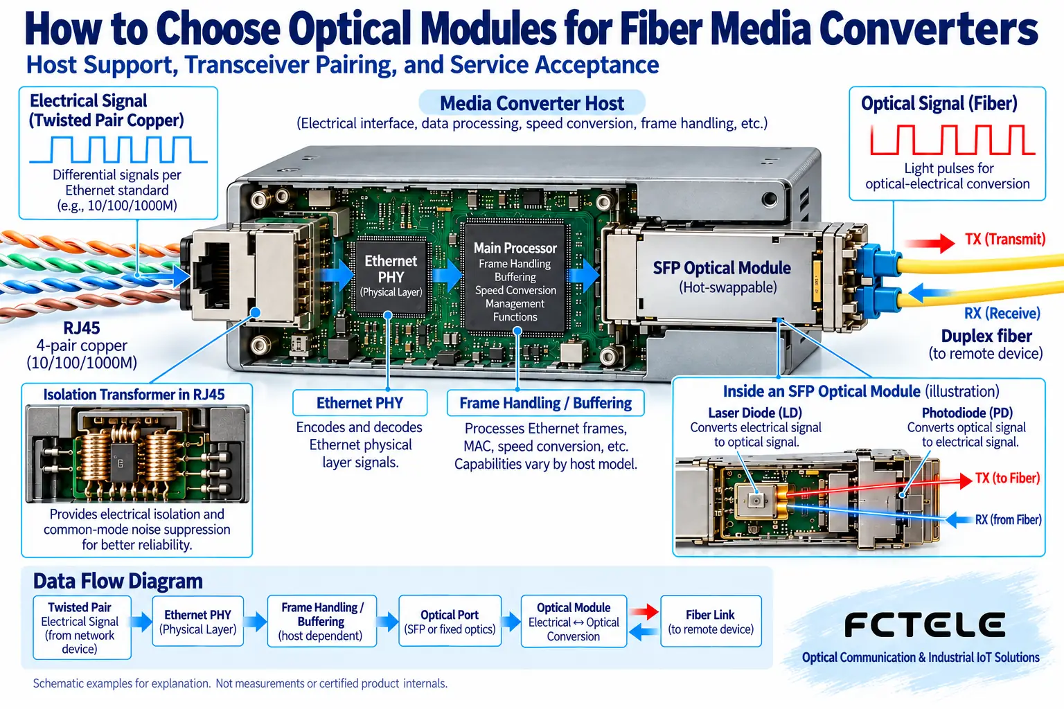
A common electrical-to-optical media converter has Ethernet physical layer circuitry on the copper side, which handles sending, receiving, and corresponding processing of electrical signals; the optical side uses fixed optical components or a pluggable module to achieve optical-electrical conversion. An optical module is usually not an independent switch, does not decide the forwarding path for the entire network, and does not automatically understand the camera images in an application. It sends the line electrical signals provided by the host into the fiber, and then converts the received light into the electrical signals the host needs.
Different converter hosts are not all implemented in the same way. Some use a media conversion approach at the same speed, while others have frame processing, buffering, or multiple electrical ports. Whether cross-speed, jumbo frames, link fault pass-through, and management diagnostics are supported depends on the host model documentation, and is not automatically obtained just by plugging in a certain SFP. Fixed optical port devices may not provide a way to replace the module on site, so the structure should be confirmed first.
2. First ask which module the host supports
If there is an SFP slot, find out the supported package, speed, and relevant vendor compatibility requirements. SFP has a similar appearance, but that does not guarantee that all line speeds and hosts support it; SFP and SFP+ appearances also cannot be used as proof of interchangeability. Host software or hardware versions may affect module recognition. The purchase list should include the complete host and module model, and the supplier should confirm the combination, rather than just writing “gigabit module”.
Some hosts only support one optical port speed. After the copper electrical port negotiates another speed, whether forwarding is possible depends on the host’s processing capability. The optical module will not automatically perform any speed conversion. If a project needs 100 Mbps terminals to connect to a gigabit optical link, confirm that the host explicitly supports that combination and test it in practice. You cannot infer that the optical port will also change speed just because multiple speeds are printed on the electrical port.
3. Why transceiver pairing is more important than identical labels
A dual-fiber link requires connecting TX at one end to RX at the other end, and the line speed, fiber type, and optical conditions at both ends must also match. Single-fiber bidirectional usually uses two different wavelengths for transmission, and the two ends must form a complementary relationship. Two modules may have different models but happen to be the correct pair; two modules with seemingly identical labels may instead not be suitable for pairing. When ordering, the A and B end positions and the matching relationship should be clearly specified.
The same interface shape does not mean the polish type, patch cords, and patch panels can be ignored. The choice between single-mode and multimode is determined by the corresponding module and line conditions, and cannot be converted by casually changing a patch cord. Contamination on the connector end face and bends in the line increase loss, so after confirming the model, the actual optical path must also be checked. When the far end is a switch or another media converter, the respective support relationships must also be checked.
4. The nominal distance is not a site pass
Distance labels are generally based on specific fiber and optical power conditions. The site line has connectors, splice points, and various additional losses, so judging by length alone is not enough. The optical power budget must relate the guaranteed output at the transmitter, the line loss, and the power required at the receiver, and must retain the margin required by the project. Do not treat typical parameters as guaranteed worst-case conditions, and do not promise “it will definitely work” when the parameters are unknown.
Short links must also check the maximum receive power. Some long-distance modules may require attenuation conditions that meet the manufacturer’s requirements at very short distances, and you cannot assume that stronger light is always better. When using an optical power meter or module diagnostic data, record the wavelength, direction, measurement location, and model thresholds. Measuring normal power only shows that one optical condition may be satisfied; correct data and service must still be verified.
5. Why buffering cannot guarantee zero packet loss
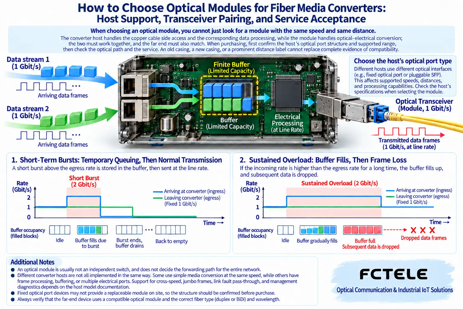
If the host supports data forwarding at different speeds, the input and output rates may differ. Limited buffering can temporarily store data waiting to be sent; for example, after a short burst ends, the queue gradually empties. But if continuous input is greater than output, the buffer will eventually fill up. How it is handled after filling up is determined by the host design and policy, and you cannot promise completely zero packet loss or no latency just because there is buffering.
You can think of the buffer as a temporary waiting area, but it cannot make the exit capacity larger. Full duplex means that the two directions of a connection can communicate at the same time, but it does not mean that one direction can carry unlimited traffic, nor does it mean that all devices have the same buffer structure. In actual networks, multiple terminal aggregation, link speed differences, and service bursts all require system design, and module selection cannot be made to carry all bandwidth problems.
6. Check temperature and diagnostic functions separately
The host and the module each have their own environmental conditions. The fact that an industrial host supports a certain temperature range does not mean that a commercial module plugged into it also meets it; similarly, a wide-temperature module cannot automatically upgrade an ordinary host into industrial equipment. Attention should also be paid to actual cabinet temperature rise, heat dissipation, and power supply. Fanless does not mean no heat is generated, and a metal casing does not prove that it is suitable for any installation environment.
Digital diagnostic monitoring can provide clues such as temperature, voltage, and optical power, but it must be supported by both the module and the host. During procurement, confirm whether this data can be read and which alarms are defined, and do not treat diagnostic capability as a guaranteed feature. When a fault occurs, record first and then replace, to avoid losing evidence; after the link recovers, check port errors and the actual service, and do not just look at the green indicator light.
7. The difference between Feichang Technology OEO products and media converters
The Feichang Technology FCM-OEO product page shows an optical signal relay or conversion structure with two SFP slots, which can be used for optical link configurations within the range explicitly supported on the page. It is not the ordinary RJ45 electrical-to-optical media converter discussed here, and you cannot infer copper auto-negotiation, frame buffering, or cross-speed Ethernet switching capability from it. The value of modular optical path configuration should be understood within its actual service and parameter range.
If the project requires electrical port access, ask the supplier to provide documentation for the corresponding electrical port media converter or switching equipment; if it is optical path relay or wavelength/mode conversion, select according to the OEO product support conditions. Both needs may use optical modules, but the host role is different. Making the product object clear can avoid buying equipment that “has an optical port but lacks the required function”.
8. Acceptance uses service to prove compatibility, not newness or age
During procurement, require traceable model, source, support documentation, and warranty information. Appearance can only reveal some mechanical problems; it cannot prove laser status, performance, or compatibility; nor can it be used alone to determine that equipment is definitely refurbished. After delivery, test with the host, far end, fiber, and terminals used in the project, and record the negotiated speed, optical status, error statistics, and actual service performance.
When high-load or environmental verification is needed, agree on the test conditions and acceptance criteria in advance. Passing the test means that the combination meets the requirements under the recorded conditions; it is not a guarantee for all protocols, all temperatures, and permanent zero failure. Keep the three layers of evidence—host support, optical path pairing, and service acceptance—so that future expansion or maintenance also makes it easier to choose a truly suitable replacement module.
Reference materials:Cisco optical link and module compatibility troubleshooting;Feichang Technology FCM-OEO product details. The illustrations are general mechanism diagrams, not the internal design or measured records of a specific media converter.
Translated from the Chinese technical article. Source first published: 2020-04-20. Source last revised: 2026-10-13T18:52:49+08:00. Read the Chinese source
