


To identify a fiber optic transmission device, the appearance can only provide clues; the model, port labels, and manual are what confirm the service. The same BNC may connect to analog video or SDI, and the same RJ45 may be used for network, serial, or management. This article teaches you to understand the differences by what circuits the signal passes through after entering the device, to avoid the misjudgment that “if it plugs in, it’s compatible.”
1. Establish Device Identity from the Nameplate
First, take clear photos of the entire unit, the nameplate, all ports, and power markings. Record the complete model, version, transmit/receive role, and the corresponding remote end. Do not just note “video fiber optic transmission device” or “eight-channel device”: eight channels may refer to video, telephone, or combined services, and interfaces may also change according to order options. For second-hand equipment or old cabinets, especially verify the nameplate against the actual boards; do not substitute another model’s manual. Photos help communication, but they need to be clear and readable; a blurry appearance is not parameter evidence.
Look for power input, video, or data markings, then check the manufacturer’s official documentation. If ports are unlabeled or documentation is incomplete, pause before connecting sensitive terminals and provide the manufacturer with the complete model and photos for confirmation. Do not judge power by enclosure size, waterproofing by metal casing, or operating temperature by the presence of a heat sink. Desktop and card-type are first of all installation forms, not sufficient explanation of video, telephone, or Ethernet services.
2. Why BNC with the Same Appearance Differs Internally
Analog composite video is a voltage that changes over time; the related front end receives it according to analog video requirements, and a digital fiber optic transmission device can sample and quantize it before transmission. SDI is digital serial video; the receive chain needs to handle high-speed waveforms, equalization, and clock recovery. Even if both devices use BNC, the signal structures they face are different and cannot be automatically converted by simply plugging them together. When conversion is needed, use equipment that explicitly supports the corresponding input and output.
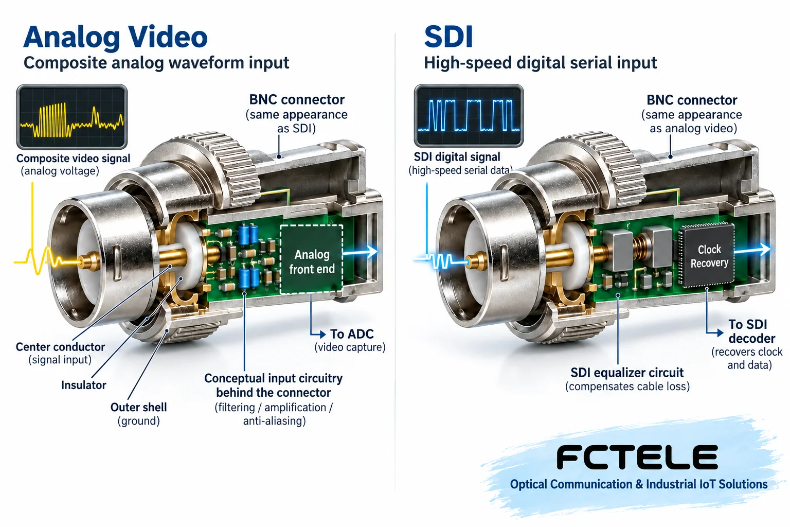
Continue by checking the format and rate. A label saying “video” does not mean it supports all video formats, and digital internal transmission does not mean the external interface is SDI. High-definition coaxial video may also have other formats and cannot be lumped together as one universal BNC service. When selecting, compare the terminal output specifications with the fiber optic transmission device input specifications item by item, then check the receive output and the viewing end; verifying only the transmitter model is incomplete.
3. RJ45 Cannot Simply Be Called a “Network Port”
RJ45 describes a common connector shape. An Ethernet service port connects to network physical layer circuits behind it and handles data frames; a serial management port may connect to serial transceiver circuits behind it for a terminal to operate the device; some service serial ports also use this connection form. Their pinouts, electrical conditions, and protocols may differ. Mixing these interfaces with an ordinary network cable may not only fail to communicate but may also create an inappropriate electrical connection.
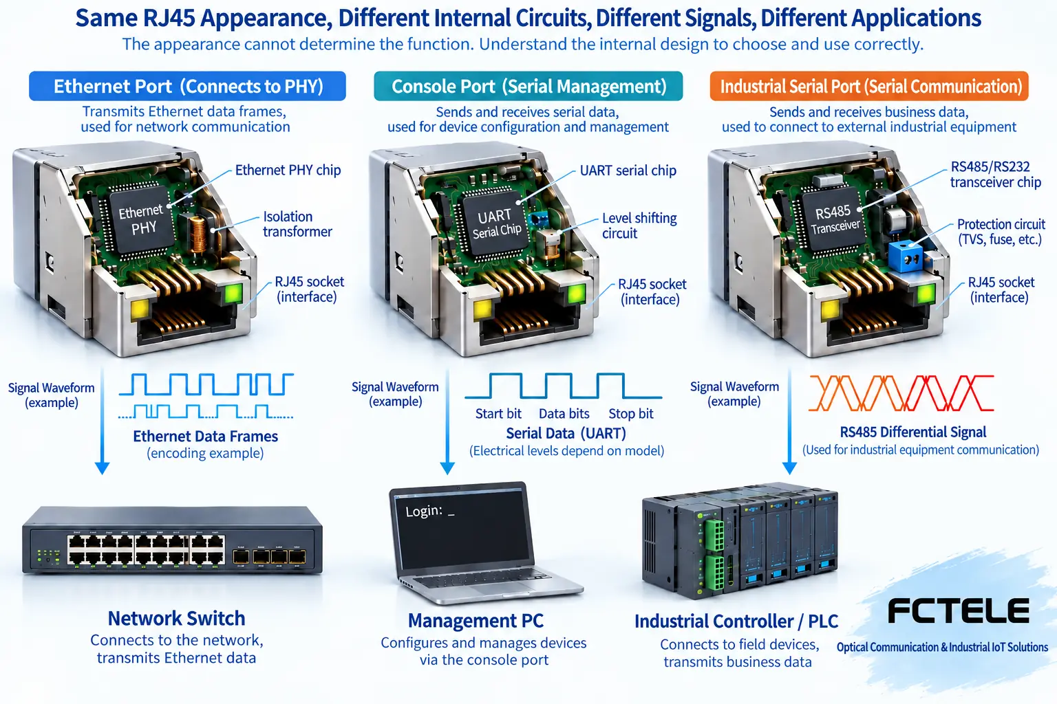
Console usually serves management and is not equal to a service forwarding port; a service serial port may carry control bytes, not an IP network. In the Feichang FCV-V4T/R details, descriptions of video and optional data interfaces can be seen, showing that identification must return to the specific model and order combination. Do not infer support for PoE, Gigabit, or a certain serial polarity from the RJ45 shape, and do not make wiring according to another device’s pinout table.
4. Optical Connectors Only Explain Part of It
Seeing SC, LC, and other interfaces allows preliminary identification of the connector family, but you still need to verify polish type, single-mode/multimode, wavelength, and the device’s transmit/receive combination. Single-fiber bidirectional devices may rely on different wavelengths to separate the two directions, while dual-fiber devices usually use separate channels for transmit and receive. Matching connectors do not mean these conditions match, let alone that any two devices can form a pair.
Transmission distance is also affected by transmit power, receive range, fiber loss, and connection points. The distance written on the nameplate usually has conditions and cannot be taken as an automatic acceptance conclusion for the actual line. Do not confirm emission by visually observing an unknown optical port, and do not use random patch cords to try out a “combination that lights up.” First identify according to documentation, then check with safe, suitable instruments; this is the basic order for protecting people and equipment.
5. Telephone and Auxiliary Interfaces Also Require Direction Identification
Telephone services require checking FXS and FXO roles; do not interconnect them at will just because the socket looks like a telephone jack. Control services require checking RS232, RS422, RS485, and other electrical standards and the actual wiring definitions; relay alarms, switch quantities, and power terminals likewise cannot be confused. Text near terminals should be interpreted with the manual; markings such as NO, NC, and COM should be used under clear function and safety conditions, not confirmed by guessing and shorting.
When the entire unit supports multiple services at the same time, drawing an interface purpose table is most helpful: what each port connects to, what signal, which direction, what parameters are needed, and how to verify. The table should come from documentation and on-site confirmation, not from classifying all sockets as “data ports.” Different boards in a chassis also need to be registered separately, because the same chassis appearance may correspond to different service combinations.
6. Indicator Lights Are Clues, Not Final Conclusions
The power light usually only indicates a certain power state; the meaning of a link light is determined by the specific implementation; a service activity light may only indicate signal activity. You cannot use “all lights on” to guarantee video quality, telephone dialing, or correct control commands. After interpreting light states according to the manual, real terminal verification is still needed: watch the image and playback, make a two-way call, or execute a known control action. Each test should record the conditions and the corresponding channel.
For example, after replacing a receiver, the link light is on but the recording end still has no picture; continue to check the output format and the transmitter’s matching information. If the management interface can be opened, it only means the corresponding management connection is established, not that all service ports are working correctly. Separating observation points from what they can prove is the only way to avoid mistaking a partial success for system qualification.
Finally, archive photos, complete model, documentation version, port purposes, and verification results. When facing unknown equipment, the correct answer is sometimes “insufficient information, confirm first,” rather than giving a guess that sounds certain. The clearer the device identity, the easier subsequent wiring, selection, and maintenance; the value of appearance identification is to guide you to check the documentation, not to replace it.
References Feichang video fiber optic transmission device interface and option details and analog video signal description. The illustrations are generic structural diagrams and cannot be used as wiring diagrams for a specific model.
Translated from the Chinese technical article. Source first published: 2024-06-26. Source last revised: 2026-10-13T17:37:33+08:00. Read the Chinese source
