


FCTEL Original Technical Article · FCTEL Technical Team
First published: 2026-10-06 · Last modified: 2026-10-06
If a capture file is missing a frame, does that prove an industrial switch lost production traffic? Not necessarily. Port mirroring sends copies of business frames to a monitoring port. Normal forwarding and copy capture pass through different queues and buffers. Knowing the observation point, direction and capacity makes packet capture more useful as troubleshooting evidence. This article describes general mechanisms. Check the relevant model documentation for actual mirroring features, copy points and counter definitions.
Open the original image for detail. Scroll horizontally to read the diagram labels at full size.
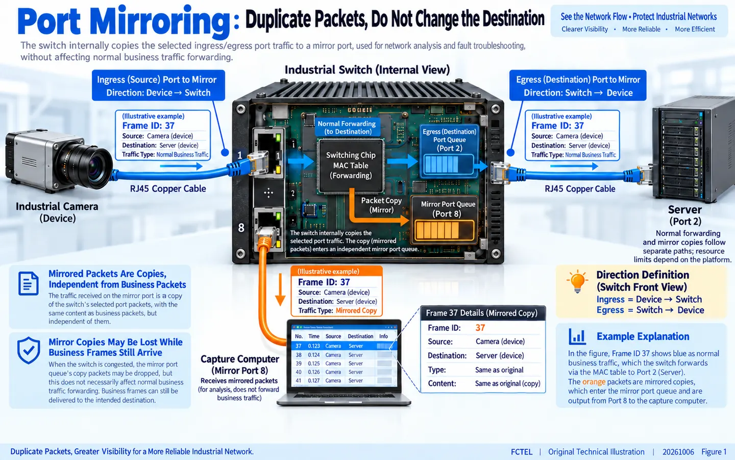
What exactly does port mirroring copy?
During normal switching, a frame enters a physical port. The switching chip identifies its destination MAC address and VLAN, selects an output, and passes the frame through a queue and transmitter. Port mirroring makes a copy at a selected observation point and sends that copy to a designated monitoring port, where a capture computer receives it. The computer is not inserted into the original business link, and normal traffic is not rerouted through capture software. Use the monitoring port as specified in the model documentation.
Separate two questions: was the business frame forwarded correctly, and did its mirrored copy reach the capture file intact? A congested mirror output may lose copies while the business continues normally. Conversely, seeing a frame in an ingress mirror does not prove that it passed subsequent filtering and reached the endpoint. Whether copying occurs before or after filtering, tag processing or routing changes depends on the hardware and firmware. One vendor's internal processing order cannot be assumed for every industrial switch.
Open the original image for detail. Scroll horizontally to read the diagram labels at full size.
Ingress and egress are relative to the switch
Ingress means an endpoint sends into the switch; egress means the switch sends toward an endpoint. On a camera access port, video normally enters the switch and control commands normally leave it. On a server-facing port, the relevant directions may be reversed. Record the source port, ingress or egress selection, monitoring destination and relevant VLANs. Otherwise, traffic outside the selected observation scope may be incorrectly reported as missing.
A business frame can enter port 1 and leave port 2. If both port 1 ingress and port 2 egress are mirrored, some implementations deliver two copies. Identical sequence numbers and payloads in a capture do not necessarily mean the endpoint retransmitted a packet. Compare the observation points, directions and protocol sequence numbers. Some devices deduplicate copies or restrict combinations; consult the manual. VLAN tags or Layer 3 fields can also differ between ingress and egress copies, so raw byte differences alone do not explain what happened.
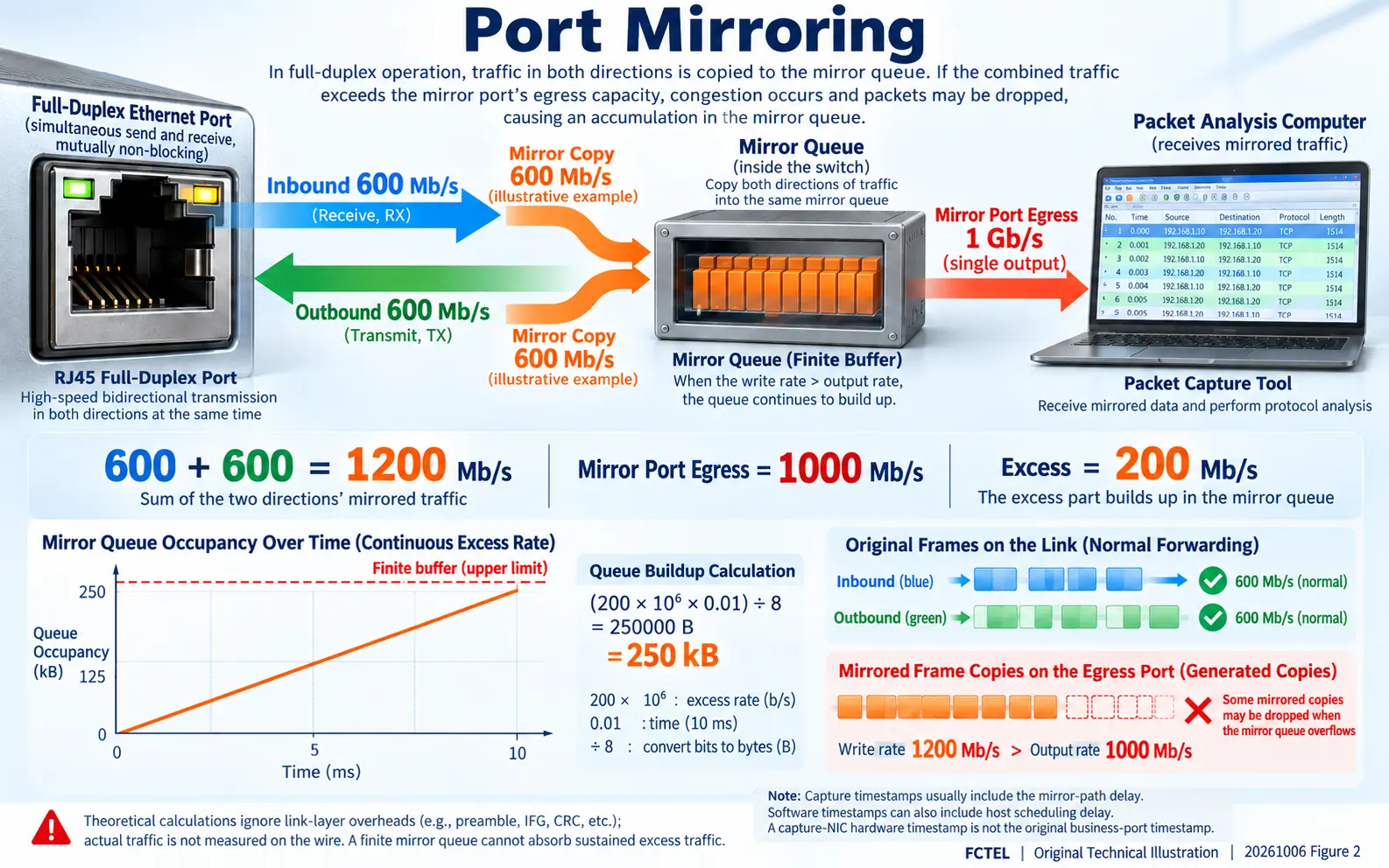
Why one gigabit source can overload one gigabit mirror output
A full-duplex gigabit port has transmission capacity in each direction. Suppose it receives 600 Mb/s while transmitting 600 Mb/s. Neither direction reaches its one-gigabit limit. However, mirroring both directions into one gigabit monitoring output creates a 1,200 Mb/s copy demand against 1,000 Mb/s of output capacity. The relevant comparison is the sum of copied traffic, rather than one utilization curve shown for the source port.
Ignoring preambles, interframe gaps and other overhead, a 200 Mb/s excess lasting 10 ms creates a backlog of 200,000,000 × 0.01 ÷ 8 = 250,000 bytes. Sufficient buffer space can hold the copies temporarily and drain them when demand drops. A sustained excess eventually exceeds any finite buffer. This calculation does not specify the mirror buffer size of an FCTEL model. A monitoring port negotiated at 100 Mb/s, several mirrored sources, or the packet-processing load of many small frames can increase capture loss.
Reduce the source scope, capture only one direction initially, and use a shorter capture window to investigate capacity. Use filtering or a faster destination only if the actual device supports it; these features are not universal. A display filter in capture software generally hides packets already collected and does not reduce earlier mirror-output traffic. Where a capture filter takes effect must also be checked for the implementation.
Open the original image for detail. Scroll horizontally to read the diagram labels at full size.
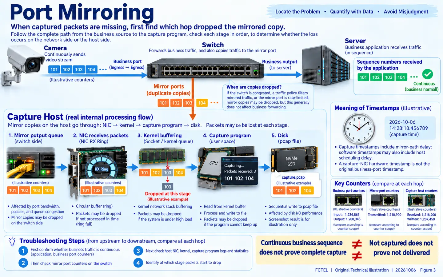
Copies can still be lost after reaching the capture computer
After leaving the monitoring port, copies pass through the computer's NIC, receive descriptor ring, driver and kernel buffers, capture application and finally storage. A stage that cannot keep up may discard packets before they enter the file. A faster switch mirror output does not automatically fix CPU, buffer or disk bottlenecks. The application's reported drop count may not cover every preceding stage.
Record business-port errors and discards, mirroring counters where available, NIC receive errors, capture-library drops and storage status separately. Counter scope, reset behavior and inclusion of filtered traffic vary, so verify the definitions. CRC errors concern received-frame integrity; queue discards concern capacity or policy. They should not all be labeled a link fault. When a sequence number is absent from a capture, check the sequence actually received by the destination application or its message logs. One pcap file alone is insufficient evidence.
The limits of timestamps, tags and retransmission evidence
Common capture timestamps record when the monitoring host receives or processes a copy, rather than when the original frame entered or left the business port. Mirroring queues, output transmission and host scheduling can add delay. Even a NIC hardware timestamp usually measures arrival at the capture NIC. Unless the documentation explicitly establishes otherwise, it is not the original timestamp at the switch's business PHY.
Mirrored captures are useful for protocol order, addresses and payloads, but should not be treated as a guarantee of microsecond control latency. NIC offloads, tag stripping and capture-length limits may also affect the displayed result. When comparing captures at two locations, check clock synchronization, observation points and filters, and retain the original files. For suspected TCP retransmission, compare sequence numbers, acknowledgments and endpoint statistics. For gaps in industrial-protocol application sequences, account for that protocol's own mechanisms rather than attributing every gap to the switch.
A repeatable field verification procedure
Save the mirroring configuration and negotiated port state first. In an approved maintenance window, select one source and capture one direction of traffic with identifiable sequence numbers. Record application counts at the sender and receiver, plus starting and ending counters on the relevant ports and host. Then keep the business conditions consistent, enable both directions, and compare copy counts and capture drops. Do not inject unverified traffic into control equipment.
If the destination application's sequence is continuous but copies are missing, investigate mirror capacity and the host capture chain first. If the application also has gaps, combine business-port errors, output discards and protocol logs to locate the fault. FCTEL's published documentation for a managed industrial switch with 24 gigabit electrical ports plus four gigabit SFP/electrical ports lists port mirroring as a diagnostic feature. That does not establish support for every platform-specific feature discussed here. Check the exact model, firmware and manual, restore the configuration afterward, and preserve the test conditions and raw records.
Technical references: Cisco documentation on SPAN mechanisms. Related FCTEL resources: Technical Articles and industrial switch product documentation (Chinese).
