


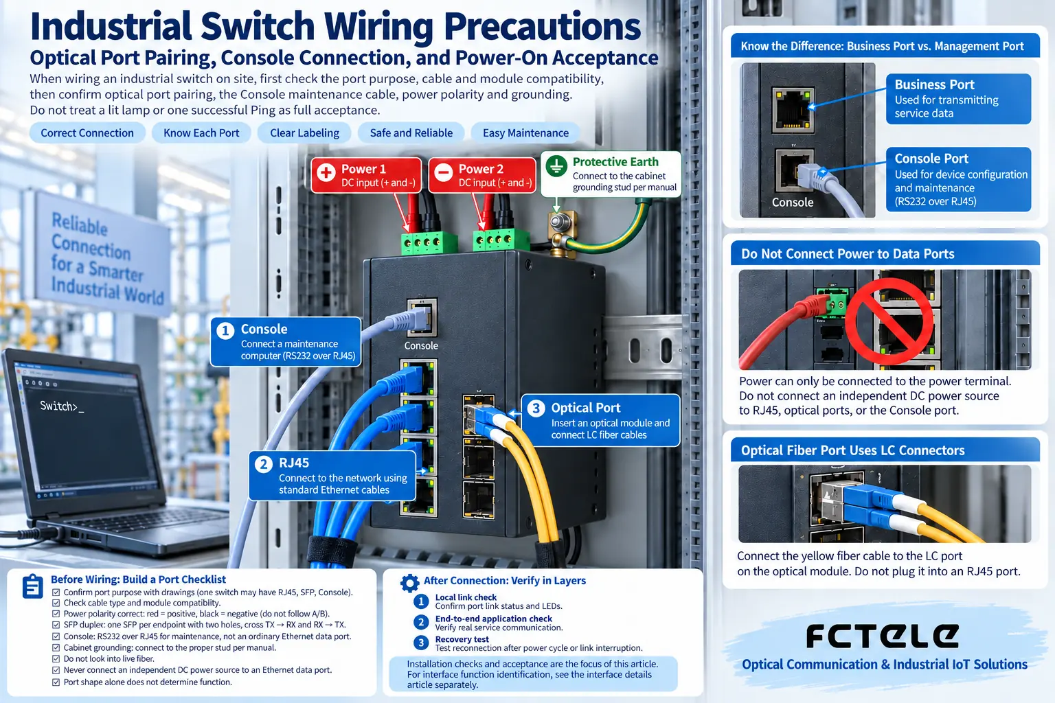
When wiring an industrial switch on site, first check the port purpose, cable and module compatibility, then confirm optical port pairing, the Console maintenance cable, power polarity and grounding. After connection, verify in layers: local link, end-to-end application, and recovery test. Do not treat a lit lamp or one successful Ping as full acceptance. This article focuses on installation checks and acceptance; for interface function identification, see the interface details article separately.
Before wiring: build a port checklist against the drawings
One switch may have RJ45, SFP, Console, power terminals and alarm contacts at the same time. First find each number and its responsibility according to the model documentation, then choose cables. Using only whether a connector can be inserted as the sole judgment may lead to plugging a management cable into a service port, or even misconnecting to a power supply terminal.
Historical local area networks once used interfaces such as AUI and BNC, but they are not common standard equipment on modern industrial Ethernet switches. If BNC appears on current equipment, it may also carry video, clock or other services. Confirm according to the device instructions; do not apply wiring methods based on old network interface names.
Copper cable access: check rate negotiation, cable and PoE budget
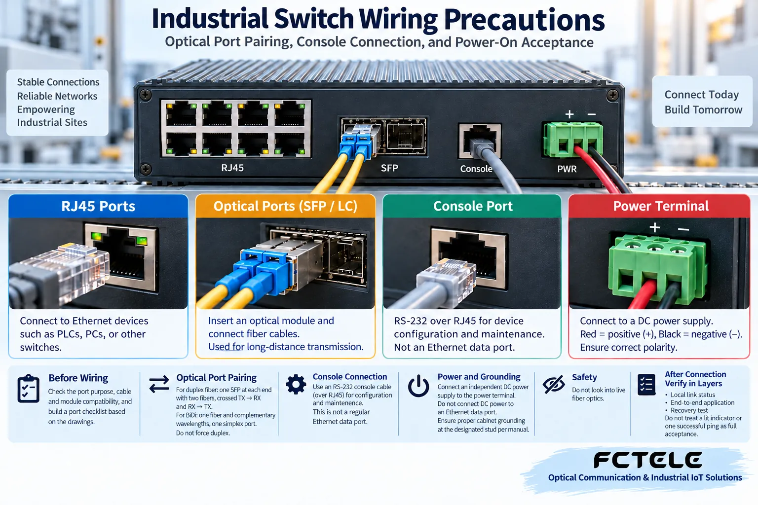
First check the rates and negotiation methods supported by both sides, then use suitable cables and connectors. A port lamp turning on indicates that the corresponding link conditions are met; it does not mean all application traffic is normal. Poor crimping, bad contact and damaged cables may cause errors or reduced rate. Do not use one Ping to judge that a cable is fully qualified.
If the port supports PoE, also check the powered device standard, single-port capability and total power budget. Ordinary RJ45 ports do not automatically supply power, and fiber does not carry PoE power. Do not casually connect non-standard passive power injectors to unknown devices.
Optical port pairing: match modules first, then check TX/RX and wavelength
SFP is a pluggable module form; the slot itself is not a complete external optical interface. When choosing a module, check the type, rate, optical standard, fiber type and opposite end supported by the host; the same connector may still be incompatible. LC and SC are connector types; they do not by themselves specify 100M, 1000M, single-mode or multimode.
Fixed optical ports already have the corresponding optical components integrated and do not need another SFP inserted. For dual fiber, a common connection is TX at one end to RX at the other end; for single-fiber BiDi, pair according to complementary transmit and receive wavelengths. Do not judge cross-model interoperability only by A/B labels or nominal kilometer ratings.
Console connection: use the correct maintenance cable to verify the management entrance
Console is often used for initial device configuration or maintenance and may use RJ45, USB or another shape. Its electrical and communication parameters are defined by the product. Serial Console should use the correct maintenance cable and serial settings; USB Console may also require a driver. Do not connect an ordinary network cable to a computer network card and expect to log in.
Some devices support Web or SSH management through service network ports; that is another entrance. You need to know the management address, the VLAN it belongs to and the permissions; in a production network, management entrances should be restricted so that maintenance operations do not affect service links.
Before power-on: check power polarity, grounding and alarm circuits
Power terminals require checking voltage, polarity, rated capability and protection requirements. Dual inputs do not necessarily guarantee truly independent redundancy; confirm the internal mechanism and external power supply scheme according to the instructions. The purpose of the grounding terminal cannot be replaced by a signal reference terminal.
Alarm relays are usually status outputs and by default cannot directly drive any load. Contact ratings, normally open and normally closed definitions, and linkage wiring should be confirmed in the documentation. Wiring involves electrical safety and should be performed by suitable personnel according to site rules.
Power-on acceptance: test link, application and recovery separately
Record port numbers, opposite ends, cables, modules and service VLANs; first verify the local link, then verify the end-to-end application, and finally test the specified recovery scenarios. Back up the configuration before production changes; when an abnormality occurs, change only one condition at a time.
For selection, you can check specific interface combinations through Product Center. If the drawing only says “optical port” or “network port”, add rate, service, module and power supply conditions; otherwise procurement and installation personnel may still understand it differently.
How to distinguish “connected” from “deliverable” during acceptance
Step one: check power and device startup status, confirm indicator lights according to the manual, and do not require all lights to be on at the same time. Step two: check the opposite end, negotiated rate and duplex status of each link; for devices with management capability, also observe whether port error counters continue to increase. Step three: verify the actual service, such as camera images, PLC communication or host computer data, rather than only testing whether the management address can be Pinged.
Finally, verify recovery capability within the approved maintenance window: when there is a redundancy design, separately check the allowed single power supply or link failure scenarios, and record service interruption and recovery. Do not directly unplug cables for testing in an unapproved production network. Devices without redundancy design also cannot promise recovery capability according to the standard of dual-power or ring-network products. Delivery records should include ports and opposite ends, module specifications, fiber pairing, power supply parameters, configuration backup and service verification results.
If you need to first understand the functional boundaries of each interface, you can read Industrial Switch Interface Details: RJ45, SFP, Console and Power Alarm; this article is used to put this knowledge into wiring checks and delivery acceptance.
The illustrations are interface and scenario diagrams and do not replace the terminal definitions and safe operation instructions of a specific model.
Translated from the Chinese technical article. Source first published: 2022-09-21. Source last revised: 2026-10-13T20:54:09+08:00. Read the Chinese source
