


A managed switch is not a device that automatically plans the network for you as soon as it is plugged in. It forwards Ethernet frames sent by terminals according to rules, and it also allows administrators to modify those rules. The correct order for initial setup is: first ensure secure management, then plan ports and VLANs, and finally save the configuration and verify real services. This article explains general operating logic and does not provide default addresses, passwords, or commands that have not been confirmed for a specific model.
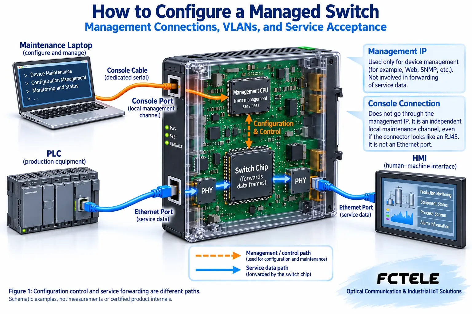
1. Distinguish the management channel from the service channel
When a PLC sends data to an HMI, the service is usually forwarded through the switch chip; when maintenance personnel open the management web page, they are accessing the device’s management service. These are two different things. A Layer 2 switch may forward services normally even without an IP address for administrator use; assigning a management IP to the switch does not mean assigning addresses to all terminals.
Management can go through a dedicated Console port or through a management address on the network. The Console is a local management channel; even if the connector looks like an RJ45 Ethernet port, it cannot be treated as an Ethernet port. Its electrical definition, cable, and serial parameters must be based on the manual. Network management requires a correct address, VLAN, and access path between the computer and the device; when crossing network segments, gateway, routing, and policies must also be considered.
2. Prepare a fallback before changing parameters
First record the model, hardware version, firmware version, and port wiring, and save any existing configuration that can be exported to a computer. Confirm the legal method to restore management, then enter the maintenance window. Do not directly restore a production device to factory settings just to find an unknown address; this may also clear VLANs, ring roles, authentication, and uplink configurations.
New devices are best debugged first in an isolated test environment. Turn off unnecessary network card connections on the computer, use known-good cables and a matching power supply, and complete the first login according to the model instructions. Before changing the management IP, reserve the new address in the address ledger, confirm there is no conflict, and know how the computer should subsequently access the new address. If you also need to change the management VLAN, first ensure the new management path works, to avoid locking yourself out as soon as you save.
3. Use a port table to explain VLANs clearly
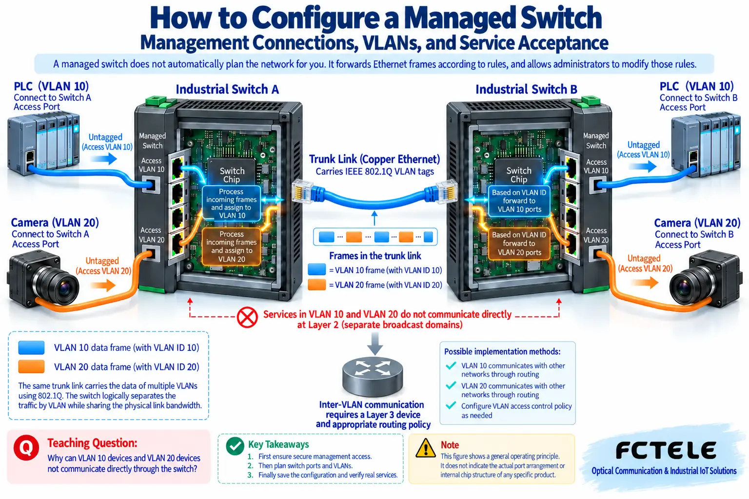
A VLAN is a virtual local area network: on the same set of physical switching equipment, it divides Layer 2 communication into different logical scopes. You can think of it as grouping frames, but it is not adding a physical wall to the network cable. Frames sent by ordinary terminals often have no VLAN tag; the switch needs to determine which group they belong to based on ingress rules, and then process them according to that group’s forwarding scope.
Assume the PLC belongs to VLAN 10 and the camera belongs to VLAN 20; the numbers are only teaching examples. Terminal access ports can be set to access mode according to device rules, meaning access to a single VLAN; if an uplink between switches needs to carry two groups of services, it can be set to trunk mode allowing the corresponding VLANs. Tags on the trunk help the other end know which group a frame belongs to, and when sending to a terminal that does not recognize tags, the tag is removed according to the egress configuration.
PVID is the default membership number for certain untagged inbound frames on a port. It is not a switch that “allows all VLANs,” nor does it by itself determine whether egress removes tags. Some devices use member ports, Tagged, and Untagged to express the same working process. You need to check ingress membership, allowed lists, and egress tagging at the same time, not just create two VLAN names.
4. Verify reachability and permitted reachability separately
A correct Layer 2 path within the same VLAN does not mean different VLANs automatically communicate. If the PLC and the host computer are divided into different network segments, a router or a device with corresponding Layer 3 functions may be needed. Conversely, once routing exists, services that were originally grouped may also access each other, requiring further access policies. VLAN is not encryption, nor can it replace account permissions and security boundaries.
After the first login, change default credentials, choose secure management methods such as HTTPS and SSH according to model support, and restrict allowed access sources. HTTP and Telnet do not provide the same level of transmission protection; they cannot be called equally secure just because both can log in remotely. Do not directly expose the production management interface to the public network; remote maintenance should use an authorized secure access solution.
5. Enable functions one by one, and actually save the configuration
For redundant links, plan the protection protocol first, then close the topology; an ordinary Layer 2 loop without loop prevention may cause a broadcast storm. For video multicast, consider both receivers and queriers; for priority functions, combine them with congestion goals. Do not turn on all switches at once just to “use all functions”; each function should have a problem to solve and an acceptance method.
Many devices distinguish between running configuration and startup configuration. Clicking Apply may only take effect immediately, and may not be retained after power-off and restart. Complete saving, export, and version marking according to the manual; verify persistence after restart only in an allowed test environment or maintenance window. Firmware upgrades also require checking version compatibility, configuration migration, and recovery methods, and do not try unknown upgrade packages during peak business hours.
6. Deliver with real services, not just by looking at port lights
First check that the management computer can still access and that unauthorized sources cannot modify at will; then check port negotiation status, VLAN membership, and uplink tags; finally have the PLC and host computer perform real request-response, and have the camera continuously send the target video. Ping is only one tool and cannot represent that multicast, throughput, and service timing are all normal.
Record error frames, discards, and traffic increments before and after changes. If contact is lost, first check status along the planned management channel and roll back; do not blindly change multiple parameters in succession. At handover, leave a port usage table, management address, VLAN table, save location, firmware version, and rollback conditions; these are more valuable than a screenshot of “login successful.”
Feichang Technology’s 10G 4-fiber 8-copper Layer 3 switch product page lists Console, HTTPS, SSH, and configuration import/export capabilities, which can serve as a selection reference when multiple maintenance channels are needed. Actual menus and commands must still be confirmed according to the delivered model and firmware; the functions supported by this product cannot be generalized as the unified operation method for all managed switches.
References:Feichang Technology managed switch product details, VLAN ingress and egress rule explanation. Third-party materials are used to verify general mechanisms and are not Feichang Technology command manuals. The illustrations are general principle diagrams, not actual test or physical photos.
Translated from the Chinese technical article. Source first published: 2020-01-15. Source last revised: 2026-10-13T18:52:49+08:00. Read the Chinese source
