


Network redundancy means that after a link, device, or power supply fails, there are still available resources to carry on the business. Common methods include spanning tree or industrial ring network protection, link aggregation, dual-device and gateway redundancy, and independent power supply and physical routing. They solve different failures, and you cannot replace design with just “connecting one more cable”; acceptance testing should also measure business interruption time, not just look at port recovery.
Starting from a failure on one production line
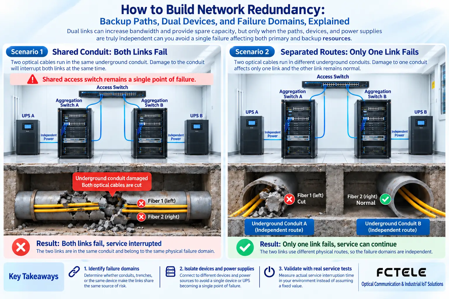
A PLC sends status to a monitoring server through an access switch. If the only uplink fiber cable is cut by construction digging, even if the PLC, switch, and server are all working normally, the data still cannot reach the center. Adding another uplink can reduce the risk of disconnection, but if both fiber cables are in the same conduit, they will still fail together when dug up; if both connect to the same aggregation switch, they will both be useless after the aggregation switch loses power. This is common failure domain: on the surface there are two copies of resources, but they share one weak point that can affect them at the same time.
Before designing, you should first list how long interruption is allowed, which devices must keep communicating, and which failures must be covered. Office file transfer and closed-loop control have different tolerances, and the same “network recovery” number cannot directly represent the effect on both types of business.
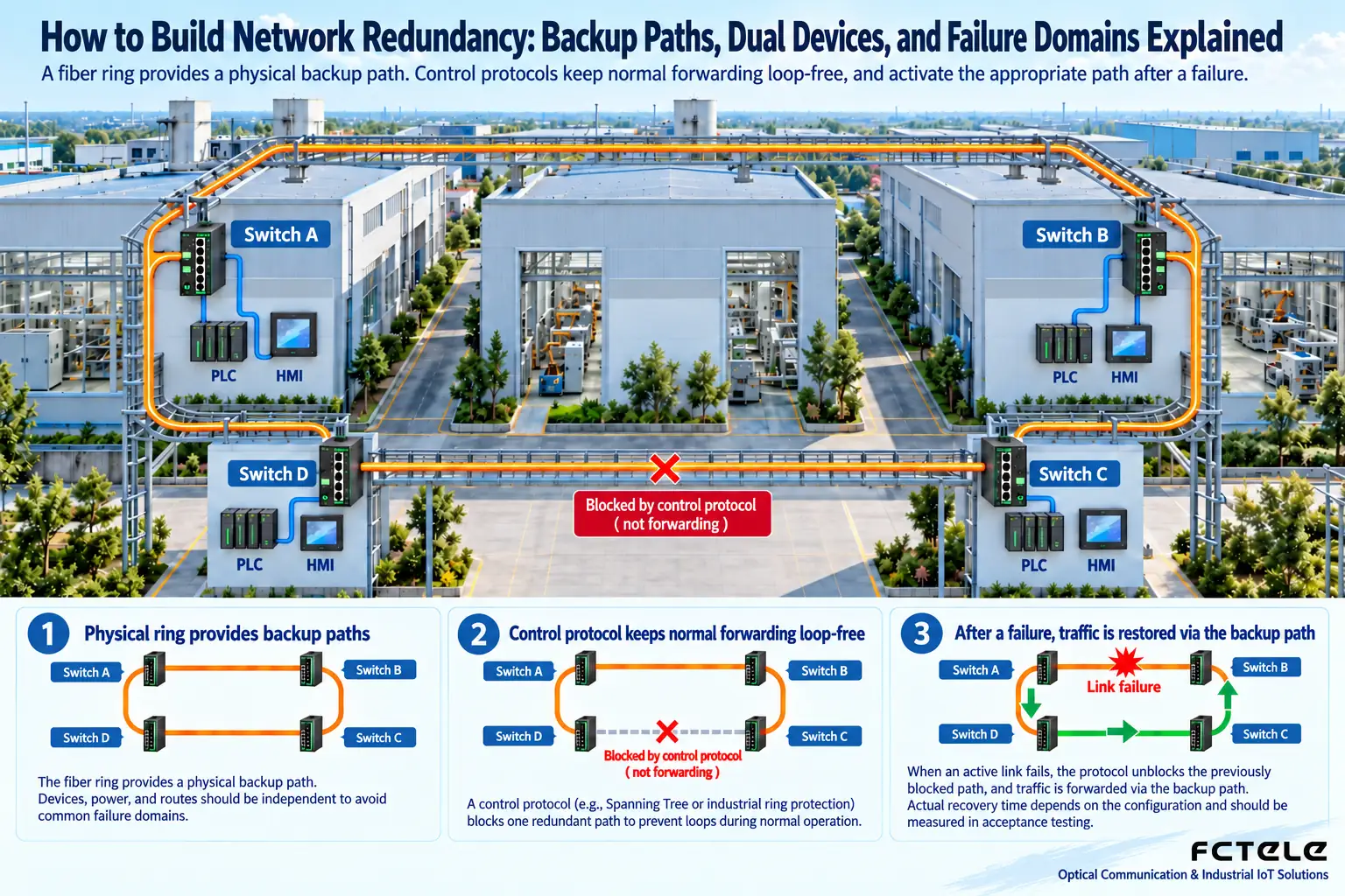
Layer 2 backup paths: prevent loops first, then talk about switching
If ordinary Ethernet switches are casually connected into a ring, broadcast and unknown-destination frames will be forwarded repeatedly, forming a broadcast storm. Spanning Tree Protocol selects a root bridge and calculates port roles so that a redundant topology keeps only a loop-free forwarding path. After a link fails, the topology is recalculated, and some backup ports enter forwarding. RSTP improves the convergence mechanism, but the actual interruption is still affected by topology, port configuration, device implementation, and terminal behavior.
Industrial ring network protocols also work around fault detection, preventing normal loops, and restoring the backup direction. When selecting models, confirm the protocol name, version, ring node limit, interoperability scope, and protection conditions, rather than assuming that all “ring network switches” can be mixed and connected. The switching time in advertising usually has specific test conditions, and projects must verify with actual load and business.
What aggregation, dual devices, and gateways each handle
Link aggregation combines multiple compatible member links into a logical connection, and after a member fails, the remaining links can still be used. Multiple traffic flows can be spread across different members, but a single flow is usually constrained by hash distribution and may not get the sum of all members’ bandwidth. When all members connect to the same device, aggregation does not protect against that device’s own failure; cross-device aggregation requires both ends to clearly support the corresponding technology, and you cannot just plug cables into two ordinary switches and call it done.
Dual devices provide another switch or router to take over the work, but they need matching connection methods and state handling.Gateway redundancy lets terminals still have a usable Layer 3 exit when one gateway fails, but it does not automatically protect remote servers, nor can it repair a disconnected access cable. For power redundancy, check whether the inputs come from independent power paths; dual power terminals connected to one adapter still share a power supply failure.
Use fault injection to prove the solution works
During an approved maintenance window, simulate one uplink disconnection, one aggregation device stopping, and one side’s power interruption, and record packet loss, connection re-establishment, and application alarms at the control end and terminal end. Do not just keep pinging: TCP connections, video streams, and PLC cyclic data may have different recovery behavior. After restoring the primary path, also check whether it flaps again, whether it switches back and forth repeatedly, and whether the remaining path bandwidth can carry peak business.
Redundancy increases ports, cables, configuration, and maintenance costs. It is recommended to match failure scenarios with protection mechanisms one by one, and then choose the necessary combination. The truly meaningful indicator is “when an agreed failure occurs, which businesses can still run and with what quality,” not how many links are lit up on the device.
Fault recovery can also get stuck outside the network
The link has already switched to the backup direction, but the application is slow to recover. This may be because the terminal is still waiting for session timeout, address table updates, or device reconnection. The network team and control team should align their observation points: record the moment of physical disconnection, the moment the backup port starts forwarding, and the moment the first valid business data arrives. These three times cannot substitute for one another.
For example, if a group of video streams still stutters after the backup uplink recovers, first compare the backup link’s carrying capacity with the cameras’ total traffic, and check server reception, multicast paths, and caching, rather than continuously shortening the ring network detection cycle. Too aggressive detection may also treat temporary interference as a failure, causing frequent false switching, so you need to trade off sensitivity and stability according to site conditions.
There is another often-overlooked scenario: the backup path normally carries no business, and only when the primary path breaks do you discover that the fiber cable or configuration has long been abnormal. Maintenance should regularly verify the health status of backup resources and keep alarms; you cannot ignore the backup path just because the primary path is working. When necessary, rotate tests during controlled windows, rather than suddenly pulling cables during production peak.
Topology diagrams should show both business connections and physical routes, marking switch cabinets, power distribution sources, conduits, and primary and backup ports. During operations handover, explain the root bridge or ring management node, normal blocking locations, switching trigger conditions, and switchback strategy. In this way, when replacing a device or modifying a port, maintenance personnel can know which configurations will affect the entire protection domain.
Reference:Cisco: EtherChannel load sharing and redundancy. Specific ring network and dual-device functions are subject to the project device manual.
Translated from the Chinese technical article. Source first published: 2024-11-26. Source last revised: 2026-10-13T23:07:12+08:00. Read the Chinese source
