


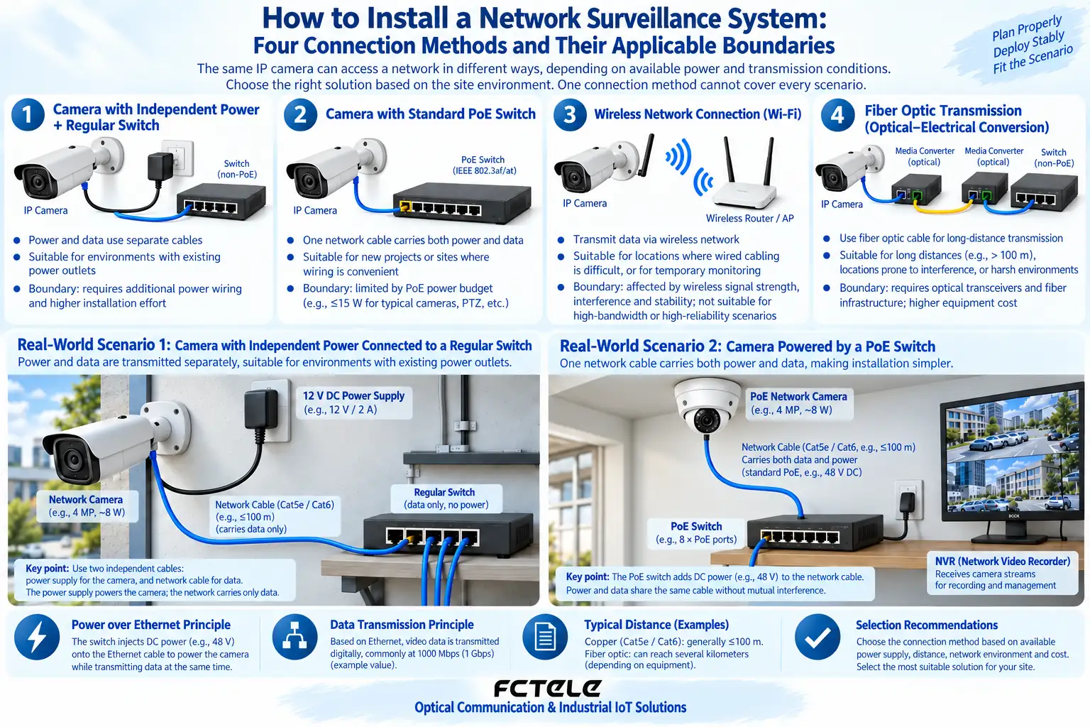
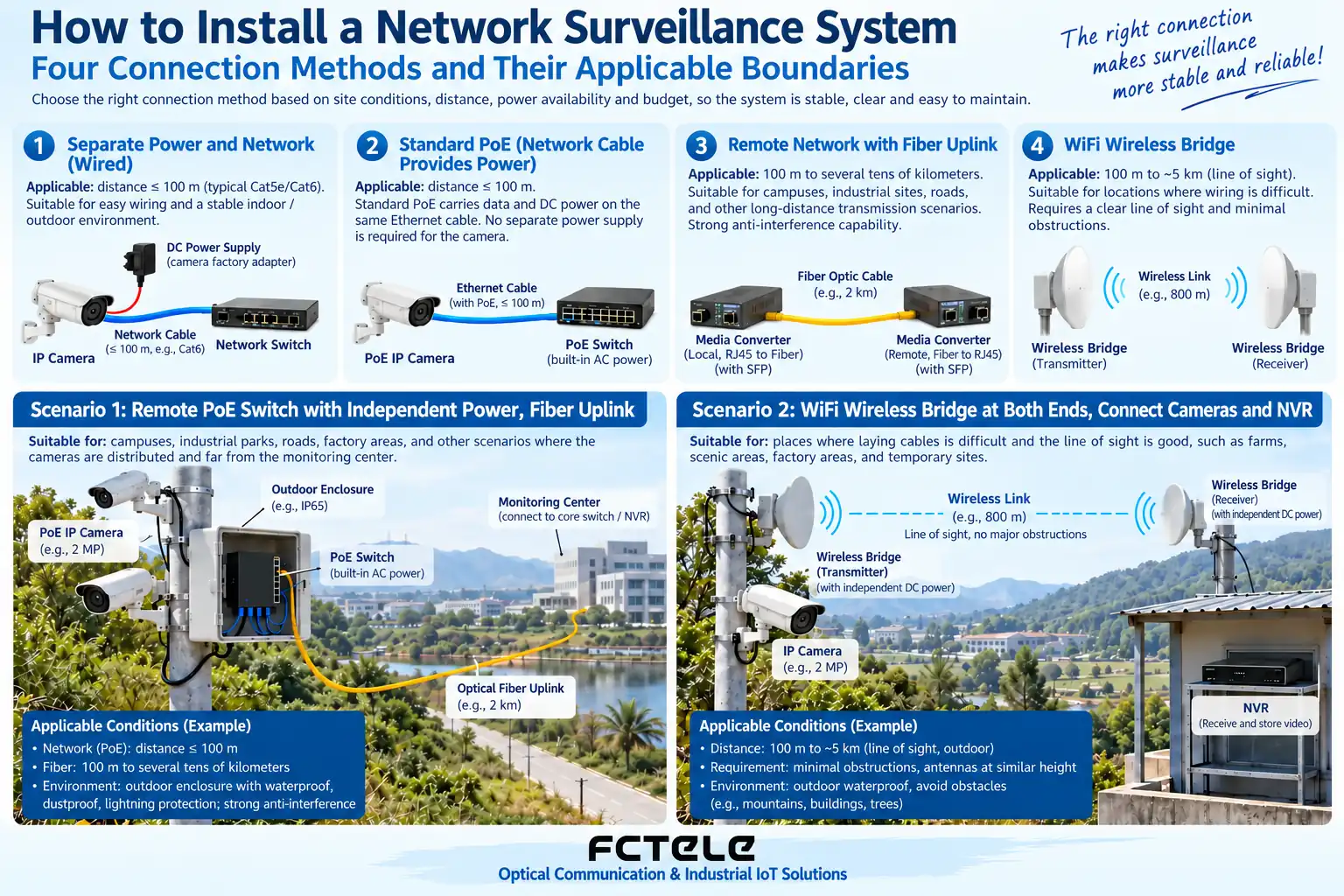
Common network surveillance connection methods include independent power plus a regular switch, standard PoE copper cable access, a remote network with a fiber uplink, and wireless bridging under limited conditions. They solve different wiring and power problems, and one connection method cannot cover every scenario. The NVR receives supported network video services, and both the link and storage need to be planned.
Method 1: Power and network each take their own path
An IP camera connects to a regular switch through a network cable and uses its own matching power supply. The NVR or management server receives the stream through the network. The advantage is that power and network are clearly separated, which suits sites that already have power conditions; at the same time, power and cables at each point must be maintained.
A regular switch does not automatically supply power to the camera. Check the power connector, polarity, and rated capability against the camera documentation. Do not connect just because the voltage numbers look similar. Outdoor power supplies and cabinets should also meet on-site protection requirements.
Method 2: Use standard PoE to reduce power cabling at each point
A camera that supports standard PoE can connect to a matching PoE switch and receive data and power over copper cable. Check the standard, per-port power, and total device power, and consider changing loads such as startup and infrared. Having enough ports does not mean the total power supply capacity is sufficient.
Do not treat passive forced power as universal PoE, and do not directly apply power to an unknown network port. If a non-PoE device needs a splitter, both its power compatibility and output conditions must be confirmed. Cable quality and length affect data and power transmission, and substandard cabling cannot be fixed by settings.
Method 3: Connect a remote switch over fiber
Across buildings or over longer runs, a remote switch or compatible transceiver can connect to the uplink through fiber. Cameras at the remote end connect through network cables, and the remote switch and cameras still need power. Fiber does not deliver central PoE power to the remote end.
Check the optical port standard, rate, single-mode or multimode, core count, wavelength, and power. Dual-fiber cross-connects transmit and receive, and single-fiber pairs complement each other. Do not treat a dedicated analog video fiber optic transmission device as an ordinary Ethernet transceiver; IP and BNC video are different services.
Method 4: Use wireless bridging when conditions are suitable
A wireless bridge can connect points that are inconvenient to cable, but line of sight, obstructions, interference, weather, capacity, and power at both ends need to be evaluated. Advertised wireless rate numbers are not the actual usable bandwidth at every site, and changes in installation position may also affect the link.
Set appropriate security measures for the bridge link and confirm the network structure. Bridge and router modes may produce different addresses and access behavior. Do not assume that the NVR can definitely access the camera just because a wireless signal is visible. Key points need to be evaluated together with reliability and maintenance conditions.
All four methods cannot do without capacity planning
Count the actual stream and peak values, consider multiple cameras sharing the uplink and the NVR receiving capability, and note that storage capacity is also related to the recording policy and retention time. Do not give universal bandwidth and hard drive conclusions for all systems based only on the number of cameras.
Network parameters include IP uniqueness, subnet, VLAN, and access policy, and service compatibility also includes video protocol, account, and encoding support. Ping reachability does not mean the picture is normal, and a picture appearing does not mean long-term recording and playback are reliable.
How to carry out item-by-item acceptance after installation
First test power, picture, sound, and control at a single point, then add points and observe simultaneous operation. Test changing loads at night, recording playback, and recovery, and record link and device parameters. Production testing must be controlled to avoid affecting existing surveillance.
Feichang Technology network devices can be checked through Product Center for specific models. Saving the topology, core numbers, addresses, and power list is more convenient for maintenance than keeping only a wiring photo. When choosing a method, give priority to meeting the actual environment and business needs, and do not advertise one approach as unconditionally best.
The images are illustrations of scientific principles and application scenarios. The interfaces, structures, and measurement values in them do not represent specific product parameters; actual specifications must be based on model documentation and on-site measurements.
Translated from the Chinese technical article. Source first published: 2019-10-15. Source last revised: 2026-10-13T22:35:50+08:00. Read the Chinese source
