


First, clarify which kind of public network is meant
“Can PCM equipment connect to a public network?” has no single simple answer, because a public network may mean the public telephone network, a digital circuit provided by a carrier, or the public internet. The three have different interfaces and service mechanisms. PCM multiplexing equipment connects to telephones, audio, or data, and then transmits them over a digital trunk that the equipment supports; whether a certain network can be used requires checking the service interface and transport conditions, not judging by the name “public network.”
When discussing a solution, write it as a complete path: where the telephone connects, what interface the PCM chassis uses, what equipment it passes through along the way, and how the far end recovers it. This can distinguish two completely different actions: “extending a PBX extension with outside-line permission” and “plugging E1 directly into a router.” PCM encoding is a method of representing a signal, and it does not automatically provide number management, internet access, or data encryption just because the network is called a public network.
Extending a telephone line that can dial outside lines
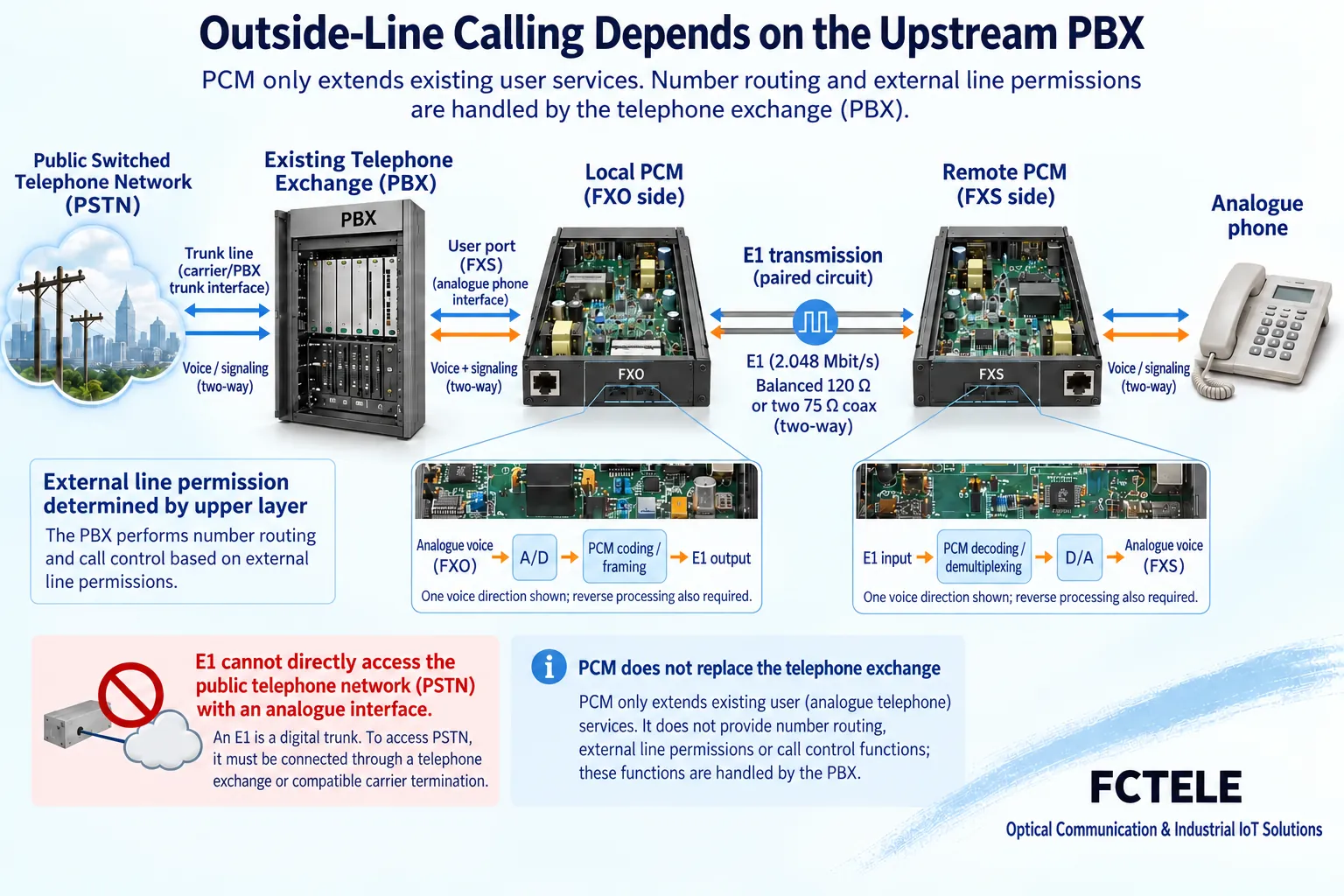
If there is already a program-controlled PBX connected to the public telephone network and outside-line permission is configured for an extension, the corresponding PCM telephone interface can be used to extend this extension subscriber line. A common relationship is that the PBX FXS subscriber port connects to the matching FXO interface of the local PCM, and the remote PCM uses an FXS interface to connect an ordinary analog telephone. Dialing, number rules, and outside-line permission are usually handled by the original PBX, and the PCM is responsible for extending the corresponding channel.
This solution does not mean the PCM equipment itself has become a public telephone exchange. Whether the remote end can dial outside lines must be checked against PBX permissions, interface signaling, and configuration at both ends; having telephone ports on both devices does not guarantee that the roles are paired correctly. When a certain model has a hotline function, it must also be verified according to its dedicated mode, and it cannot be inferred from this that all telephone ports support arbitrary dialing, number assignment, and outside-line access.
A carrier E1 circuit is not an internet network port
An E1 circuit provided by a carrier can be used for digital connections that comply with the interface and service agreement, but the line type, framing method, available time slots, signaling, and timing requirements should be confirmed. Whether E1 PCM equipment can connect depends on whether it matches the conditions of that circuit; it cannot be said broadly that E1 can only be used for self-built private networks, nor can it be assumed that all carrier lines can directly connect to the same type of multiplexing chassis.
E1 electrical interfaces may use different impedance and connector arrangements, and the transmit and receive directions need to be paired according to the documentation. Even when an RJ45-shaped socket is used, it may still be E1 and must not be treated as an Ethernet port connected to a switch. Before connection, request service delivery parameters and test requirements from the line provider, then check the PCM model. Clarifying the electrical, framing, and clock conditions of the line is more helpful for finding interoperability problems than only recording “2M leased line.”
Transport over an IP network requires a dedicated transport mechanism
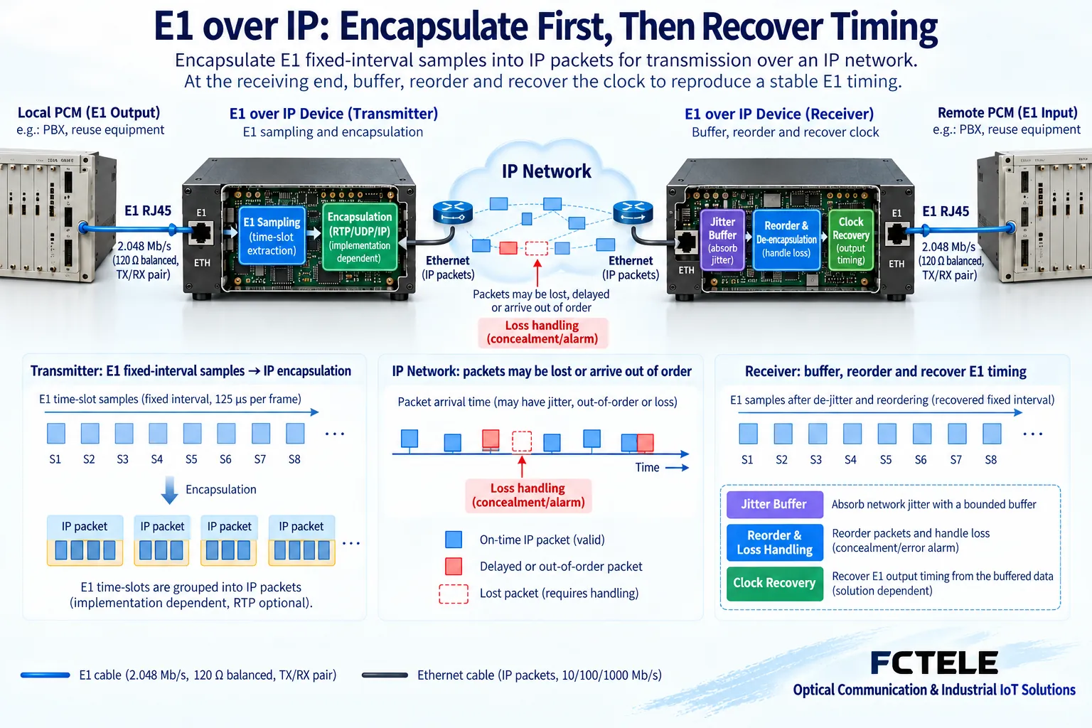
E1 is a continuous, timed digital line, while an IP network transmits packets one by one. To send E1 over an IP network, equipment supporting the corresponding circuit emulation is needed to encapsulate the line data into packets, buffer it at the far end, output it at the specified pace, and recover timing. SAToP described in RFC 4553 is a type of TDM circuit emulation mechanism that can help explain this difference, but the specific equipment still needs to confirm supported modes and compatibility at both ends.
An ordinary Ethernet switch, router, or VPN tunnel will not automatically complete E1 encapsulation and timing recovery. A converter with an Ethernet interface may also simply carry Ethernet frames over E1, which is the opposite direction from E1 over IP. Therefore, the requirement must clearly state whether it is “Ethernet service over E1” or “E1 circuit over IP,” and it cannot be summarized only as “E1 to Ethernet,” so that procurement and acceptance do not select the wrong function.
Jitter and packet loss on the public IP affect line recovery
The interval between packet arrivals may vary. The receive buffer is used to absorb delay variation within a certain range and then output at the line pace. Insufficient buffering may cause missing data, while increasing the buffer adds corresponding waiting time; lost packets also cannot be automatically recovered by the buffer. Therefore, a public IP connection being “pingable” does not mean the TDM service has the required continuity and delay conditions.
The solution needs to observe packet loss, delay variation, timing recovery, and actual telephone performance on the actual transport network. Network quality-of-service arrangements and line assurance conditions should correspond to the service requirements. The internet’s nominal bandwidth being greater than 2M cannot be taken as evidence that E1 circuit emulation will definitely be stable; nor can it be promised without testing that the public network will not affect voice or that all abnormalities can be automatically recovered.
Communication security and transmission performance are verified separately
VPN or other encryption mechanisms can protect IP communication under the corresponding configuration, but they do not thereby eliminate packet loss, delay variation, or timing problems. PCM multiplexing equipment is not inherently an encryption device, and telephone encoding and time-slot organization cannot replace access control. When confidentiality, identity authentication, or network isolation is required, it should be clearly stated which device and configuration provide the corresponding capability, and then verified independently.
Management interfaces should be assigned accounts, permissions, and accessible networks, and service ports and network management ports should be separated in the drawings. For remote maintenance, do not open console services to uncontrolled networks merely because it is convenient. Synchronization success at the line level and correct execution at the security policy level are two different acceptance results; neither being normal automatically proves that the other is normal.
Use three checklists to complete selection
The first is a service interface table for both ends, stating FXS/FXO, audio or data ports, and the actual equipment; the second is a transport conditions table, stating the E1 circuit, optical transmission, or IP circuit emulation and the corresponding parameters; the third is a management and permissions table, stating the configuration entry point and access scope. This shows whether a PCM chassis, transmission equipment, gateway, or existing PBX cooperation is needed, rather than letting one device name carry all functions.
The channel mapping and clock diagram for both ends should also be kept. If primary and backup lines are planned, confirm whether the backup transport has the same service capability and a reasonable timing relationship, rather than only verifying that the backup network is reachable. Optional functions in product documentation must correspond to the actual version; the capabilities included in a certain series cannot be treated as all being configured in the currently purchased chassis.
Accept the public network solution according to the actual service
For telephone extension, first check the roles and mapping, then test internal calls, authorized outside lines, two-way voice, and hang-up release. For a carrier E1 solution, check electrical, framing, clock, and service channels according to the delivery conditions. For an E1 over IP solution, in addition to these items, also test line recovery and actual calls under changing packet network conditions. Loopback or connectivity tests should note their coverage and do not replace complete service acceptance.
For example, if a remote office needs to use the headquarters PBX’s outside lines, first confirm the existing extension solution and trunk conditions; if only the public internet is available along the way, then evaluate whether to use circuit emulation or choose another suitable telephone networking method. This is a method of solution judgment, not a performance promise under a certain network. Only by implementing telephone functions, line transport, and security requirements separately can one accurately answer under what public network conditions a PCM device can be used.
Documentation note: The principle diagrams have been checked against technical content and are used to explain general mechanisms; they are not product photos or measured records. Specific interfaces, modes, and capabilities are subject to the selected model, version, and on-site verification.
Verification references: ITU-T G.703: Electrical characteristics of digital interfaces
ITU-T G.704: Frame structures for digital interfaces
RFC 4553: TDM circuit emulation over packet networks
Feichang Technology E1 PCM multiplexing equipment
Translated from the Chinese technical article. Source first published: 2021-09-13. Source last revised: 2026-10-13T13:23:07+08:00. Read the Chinese source
