


Fiber media converter troubleshooting can begin with six common symptoms: abnormal power, no optical link, no copper link, an active link with no network communication, slow performance or frame loss, and intermittent disconnections. These are six diagnostic entry points, not six predetermined failed parts. Assess each using both ends’ states, parameters, and actual tests.
1. For Power Problems, Check the Supply First
Verify rated supply values, polarity, contacts, and stability, measuring only under the required safe conditions. Do not energize an unidentified interface. A shared cabinet supply fault may affect both the converter and the terminal. Interpret the power LED according to the specific model instead of assuming that every device uses the same definition.
Check whether the symptom coincides with loads starting, temperature rise, or cabinet environmental changes. For dual inputs, establish the actual sources: two inputs connected to one failing source do not provide independent protection. Repeated restarting changes the symptom but does not prove that the cause has been removed.
2. If the Optical LED Is Off, Verify Pairing First
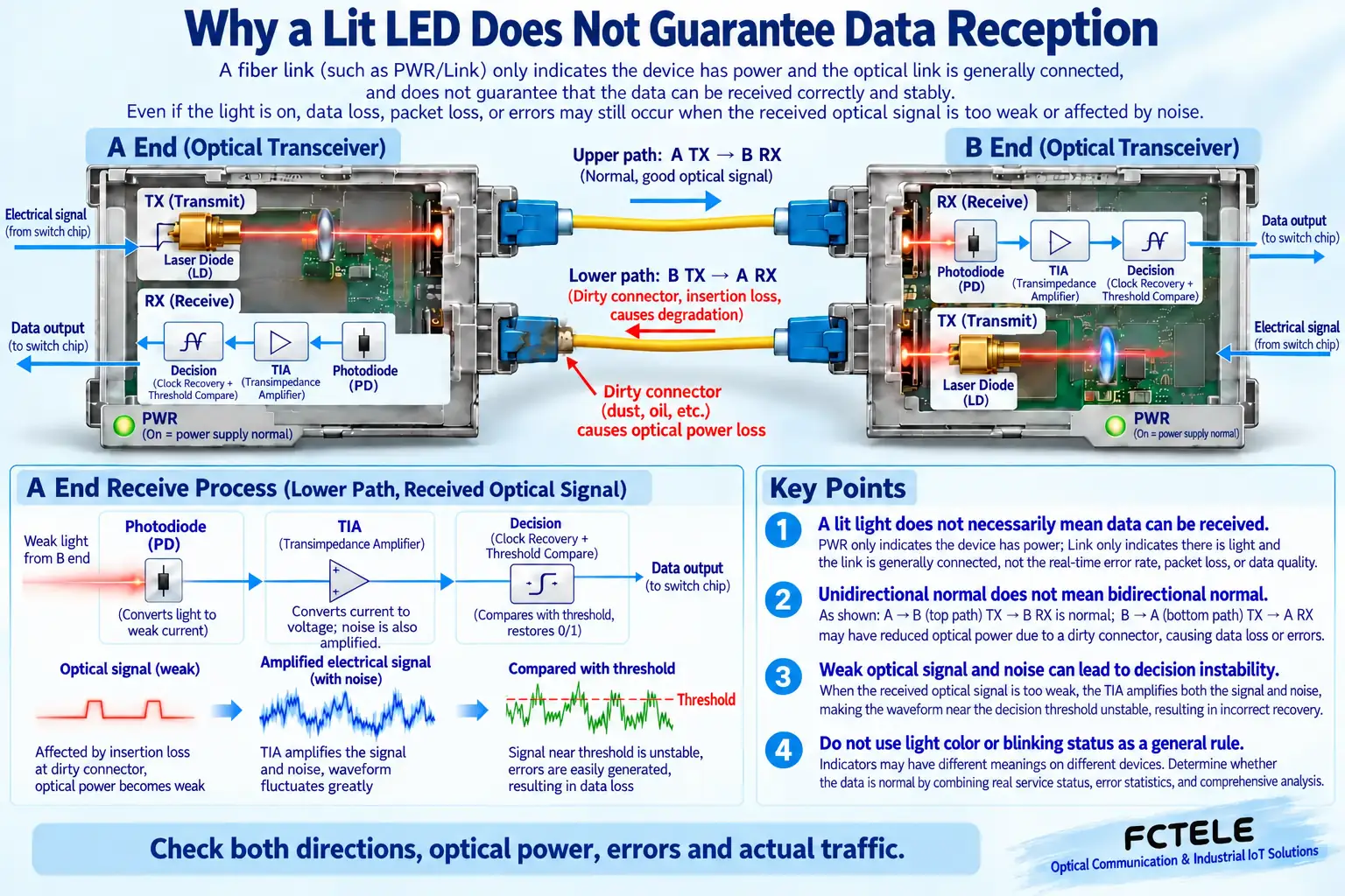
Check protocol, rate, fiber type, fiber count, wavelengths, and transmit/receive directions. Dual-fiber TX connects to the opposite RX; single-fiber units require complementary parameters. Both A and B can transmit and receive. Matching connectors or nominal distances alone cannot establish compatibility between dedicated optical protocols.
Test the two units together with a clean, known-compatible short patch cord before connecting the site circuit. Compare optical power with the receiver’s permitted range: weak and excessive input can both cause problems. Follow laser-safety procedures for inspection and cleaning, and never look into an optical port.
3. If the Copper Link Is Down, Start with a Known-Good Short Cable
Check terminal power, ports, and negotiation capabilities. Isolate the problem using a compliant short Ethernet cable and a working terminal. Copper-port rates and settings must match the opposite end; a healthy optical link does not prove a healthy copper link. Where a terminal requires PoE, check power-delivery capability separately.
4. For Active LEDs but No Network Communication, Check Configuration
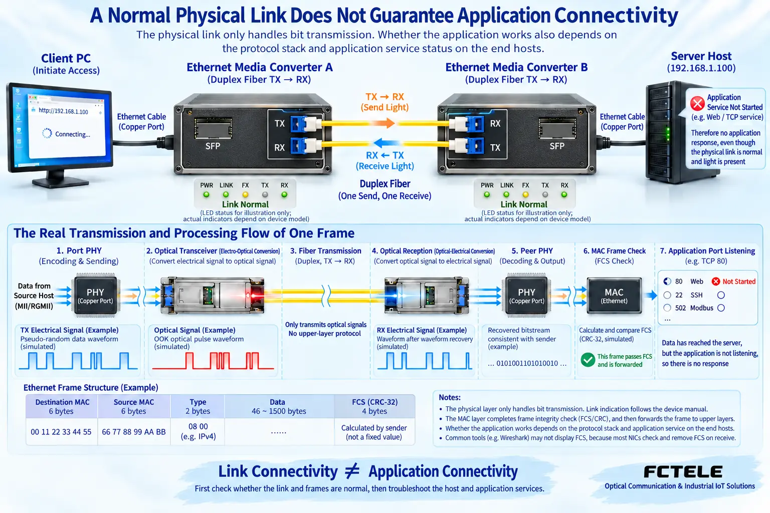
Check IP-address uniqueness, subnet, gateway, VLANs, and access policy, and confirm that the target service is running. Successful ping does not guarantee application operation, while blocked ping may reflect policy. Verify the real video, data, or control service instead of swapping optical patch cords indefinitely.
After changes to an existing system, compare original and current settings, including permitted uplink traffic and port roles. A basic converter mainly extends the transmission medium; it does not automatically replace a router or service-protocol converter.
5. For Slowness and Frame Loss, Locate the Bottleneck First
Observe link errors, optical power, and traffic, then investigate shared uplinks, end devices, CPUs, and storage. A gigabit label does not mean that every application achieves gigabit throughput, or that each connected terminal simultaneously receives the full uplink capacity. Record test paths and loads.
If only one application fails, check its service ports, authorization, and processing capacity. More retries may worsen congestion and should not be a default repair. Comparing short-link and site results helps separate equipment issues from circuit issues.
6. For Intermittent Disconnections, Record the Conditions
Record times, affected direction, temperature, supply changes, and optical-power changes. Look for correlations with motors, storms, or load startup. Substitute verified compatible components one at a time; replacing everything at once leaves the original cause uncertain.
How to Close the Maintenance Loop
Keep baseline optical power, error counters, configuration, fiber identifiers, and service behavior, then test sustained operation and recovery. Check Feichang models in the Product Center. Several of these six symptoms may coexist. Follow evidence rather than treating one LED table as a universal diagnosis.
For maintenance involving production equipment, arrange an authorized maintenance window and confirm interface and firmware compatibility before replacement. Identify unknown optical ports first rather than repeatedly reconnecting them experimentally. Associate every change with records so that future work can use established causes instead of repeating guesses.
The images illustrate scientific mechanisms and application scenarios. Interfaces, structures, and measurement values shown are not specifications of any particular product; use model documentation and actual site measurements for real limits.
Collect Evidence by Symptom to Avoid LED Misinterpretation
The same failure to communicate may originate along completely different paths. If copper Link is absent, first confirm opposite-end power and that the port is enabled, then check cable category, length, and negotiation. If copper Link is normal but the optical state is abnormal, verify speed, single-mode or multimode fiber, duplex crossover, or complementary single-fiber wavelengths. LED names, blinking patterns, and color meanings vary by model. Use its manual rather than applying an old article’s six-LED rules to every device.
For a one-direction failure, label the fibers A TX to B RX and B TX to A RX, and record receive conditions at both ends. Healthy incoming light in one direction does not prove a healthy return. Compare received power with the corresponding module’s sensitivity and maximum input: excessive and insufficient power can both cause problems. There is no universal normal dBm band. Never illuminate a port with an ordinary flashlight or look into a fiber; invisible light can also cause injury.
For intermittent behavior, record disconnection times, temperature changes, service load, and power alarms. Check connector contamination, loose mating, tight bends, and supply behavior under load one item at a time. Changing the supply, card, and configuration simultaneously makes the cause unknowable after recovery. Confirm that the source is off according to the safety procedure before connector inspection, use suitable end-face inspection equipment, and inspect again after cleaning. Casual wiping can leave residue or scratches.
When frames travel in both directions but the application still fails, inspect host addresses, routes, VLANs, access policies, and service listeners. Establish how far the request reaches and where the reply stops. Feichang managed-converter documentation describes corresponding status-management and fault-linkage features. These help gather evidence but cannot replace service verification; confirm versions and pairing scope first. After recovery, preserve sustained bidirectional tests and changes in port counters rather than accepting all LEDs being on as completion.
Product information:Feichang B-series Gigabit Fiber Media Converter;Feichang Managed Fiber Media Converters. Management, power, and optical options are not interchangeable across products; confirm the ordered model. Images are generic mechanism illustrations with simulated waveforms, not measurements or cutaways of a particular product.
Translated from the Chinese technical article. Source first published: 2019-10-15. Source last revised: 2026-10-13T17:09:56+08:00. Read the Chinese source
