


LEDs and successful pings show only that part of a path works, not continuous reliability under actual load. Testing should answer three separate questions: do copper and optical interfaces match, is received light within its permitted range, and does the complete unit sustain bidirectional traffic under agreed load and environment? Establish a known-good short-link baseline before adding field conditions to distinguish device, cable and tool limits.
1. Define the equipment under test
A converter connects Ethernet electrical and optical signaling. The copper PHY handles twisted-pair signals, the transmitter converts electrical information to light and the peer receiver converts it back. Switching architectures also forward and buffer frames. Negotiation success and complete data delivery are therefore different. Adequate power cannot exclude copper, configuration or forwarding problems.
Record both models, hardware/firmware versions, copper speed, optical specifications, fiber mode/count and power arrangement. Duplex TX must reach remote RX; single-fiber units need complementary wavelengths specified by the manual. Interface appearance is insufficient. If testing a pair, report results for that pair and its jumpers, not independent performance of one unit.
Test tools have limits too. Computer NICs, processors, disks and software may bottleneck first. Directly connect test endpoints to confirm they achieve the planned load before inserting converters. Keep settings consistent. Dedicated Ethernet testers control frames and counters; computer tools help test applications. Their result definitions are not interchangeable.
2. Use an isolated link and test directions before simultaneous load
A common setup connects tester port 1 by copper to converter A, fiber to B, then copper back to tester port 2. Test 1→2 and 2→1 separately before simultaneous load. This exposes directional faults that a one-way test or average rate may hide.
Start with short, clean jumpers of known specifications. Check speed and duplex, and verify count relationships at low load. Agree frame lengths, VLAN tags, direction, load, duration and counting rules beforehand. Increase load gradually while observing receive/error counters and link changes. A Gigabit link does not guarantee identical application payload throughput.
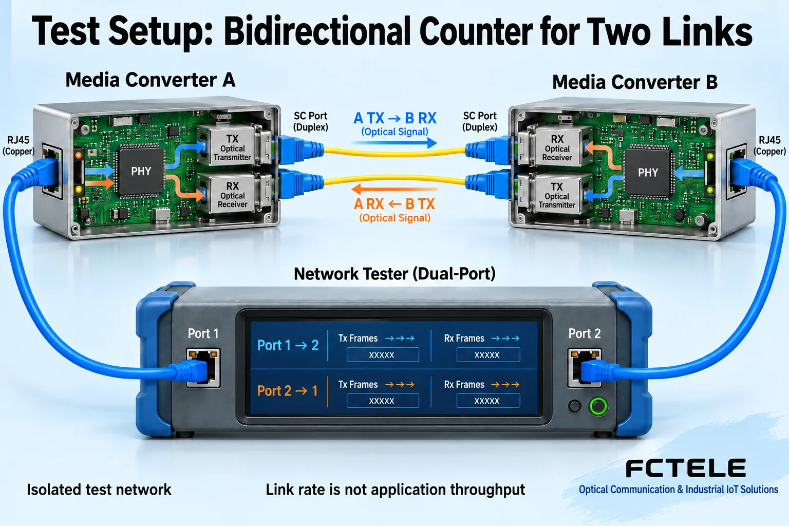
RFC 2544 provides laboratory benchmark methods and reporting guidance for throughput, loss and delay, but invoking its name is insufficient. RFC 6815 makes the isolated-test boundary explicit. Do not run such overload tests directly on production traffic networks. Agree separate nondisruptive field acceptance methods, maintenance windows and stop conditions.
3. Power meters measure absolute power; loss comparisons need consistent conditions
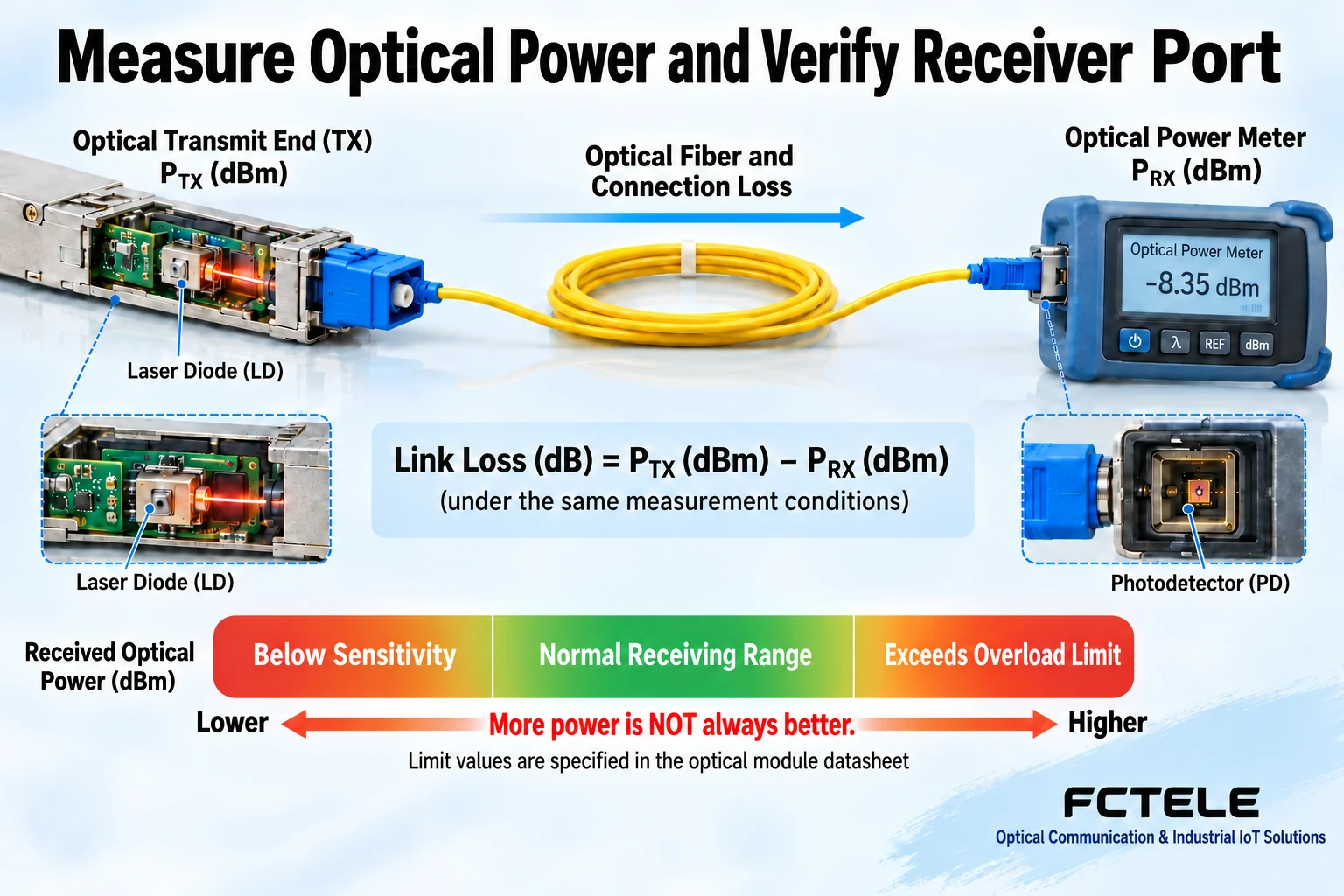
A power meter measures output-port or fiber-end power, commonly in dBm. dB commonly expresses a power ratio or link loss. Compare transmitter and post-fiber power using consistent wavelength settings, references, adapters and instrument conditions. Inspect and clean end faces, follow meter procedures and never look into a port to check for light.
Received light is not simply better when stronger. Weak input can fall below sensitivity and strong input above overload limits. Check the exact interface window and design margin. A meter at the fiber end is a disconnected measurement, not an online converter operating in that same arrangement. Restore connections and test service afterward. One passing power reading is not certification of the entire fiber.
4. Distinguish frame loss, physical bit errors and application speed
Frame-loss rate compares transmitted and valid received frames. Physical bit-error rate compares incorrect bits with total test bits. They differ: congestion can drop frames without optical bit errors, and unexpected counters can reflect test settings. Physical BER tests need appropriate interfaces, modes and instruments. A computer packet-loss percentage cannot simply be renamed BER.
Ping mainly shows reachability and round-trip response; sparse packets cannot represent heavy-load performance. Application speed also depends on protocol overhead, windows, host capability and concurrency. Retain raw frame/error counts, direction and tool settings rather than only a green pass screenshot. An optical eye diagram requires suitable optoelectronic reception and measurement equipment, not an ordinary scope probe attached to fiber.
5. Turn model features into acceptance items
The FCTEL remotely managed single-optical/single-copper Gigabit series describes local/remote management and LFP. For the applicable version, verify endpoint status in isolation and simulate authorized copper or fiber breaks separately to check indication and recovery. Management helps isolate faults but cannot replace meters or frame tests. Unmanaged versions cannot be accepted against managed capabilities.
Arrange power, temperature/humidity and endurance tests against exact manuals and project requirements. An old article set of voltages, temperatures and hours is not universal. Qualified personnel with suitable equipment should perform environmental, safety and EMC tests. Ordinary users should not vary mains voltage or dismantle live equipment. Record environment, cooling, load, restarts and link anomalies rather than simply whether the case feels cool.
6. Deliver reproducible records
If a Gigabit pair works on short fiber but loses frames intermittently in one direction on the field cable, keep other conditions unchanged. Compare receive power, end faces and connections at both ends, then copper errors and frame counts. Do not immediately replace both converters. One variable at a time identifies which action helped.
Retain equipment identities, topology, cable/optical specifications, tool versions, power/environment, traffic settings, per-direction results and acceptance basis. Passing applies only to tested conditions. Untested extreme temperatures, lifetime or certifications cannot be declared passed incidentally. Another engineer should be able to reproduce the test.
Reference note: benchmark scope follows RFC 2544 and RFC 6815; product features follow FCTEL managed converter categories and single-optical/single-copper Gigabit series details, subject to the exact version. Figures show generic mechanisms, not measurements or product photographs.
Translated from the Chinese technical article. Source first published: 2019-10-24. Source last revised: 2026-10-13T15:39:27+08:00. Read the Chinese source
