


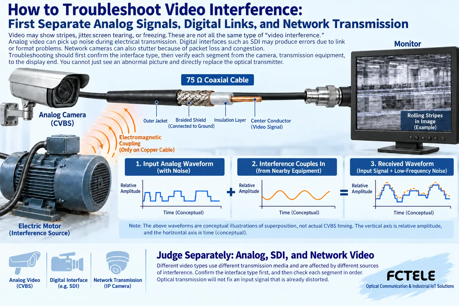
Stripes, jitter, screen tearing, or freezing in a video picture are not necessarily all the same kind of “video interference.” Analog video may pick up noise during electrical transmission, digital interfaces such as SDI may produce errors due to link or format problems, and network cameras may also stutter because of packet loss and congestion. Troubleshooting should first confirm the interface, then verify segment by segment along the camera, transmission equipment, and display end. You cannot just see an abnormal picture and directly replace the optical transmitter.
First know what signal the device actually outputs
A round connector on the camera housing does not mean all devices output the same signal. Traditional composite video, SDI, and other high-definition video interfaces may use similar connectors but have different electrical formats and device requirements. Network cameras usually put already encoded images into network packets and transmit them over Ethernet. You need to check the camera model, output settings, and receiving device instructions to confirm they belong to the same compatible link.
Take traditional CVBS composite video as an example. The signal contains information such as brightness, chroma, and synchronization, and the receiving end relies on these changes to restore the picture. SDI is a serial digital interface and does not become analog composite video just because it uses coaxial cable. The two types of equipment cannot be substituted for each other just because the connectors fit. Writing the signal type on the link diagram first can reduce later cases of mistaking a format error for electromagnetic interference.
Why analog waveforms easily carry interference along with them
When an electrical signal passes through copper cable, line loss changes the waveform, and nearby motors, power supplies, or other lines may also introduce extra changes through electromagnetic coupling. What the receiver sees is the total signal that actually arrives, not a list that can automatically separate “picture” from “noise.” When interference is superimposed on synchronization or picture-related parts, it may appear as stripes, unstable picture position, or degraded detail.
Coaxial cable shielding and proper termination help maintain transmission conditions, but damaged shielding, poor connector contact, or unreasonable wiring may still introduce problems. You cannot treat “using coaxial cable” as an absolute guarantee of no interference, nor can you assert that ordinary twisted pair is naturally better than any coaxial cable. Twisted-pair video transmission requires matching sending, receiving, and adapter circuits, and the actual effect depends on the entire system.
Power and ground potential problems cannot be judged by dangerous tests
Unstable front-end power may affect camera operation, and the power supply of the receiving device may also cause abnormalities. Observing whether the problem appears as motors start and stop, at night when fill light turns on, or with other load changes helps determine the direction of inspection, but correlation is not final evidence. You need to check the supply voltage, polarity, power, and power supply method required by the device, and have personnel with the appropriate capability inspect it.
You cannot treat the old text’s “try a different 12V battery” as a universal method for all cameras. Some devices use PoE or different voltages, and randomly changing the power supply may damage the device. You also cannot remove protective grounding just to eliminate stripes. Protective grounding is related to personal safety. Signal reference, cable shielding, and equipment protective grounding have different purposes; work involving equipotential bonding, grounding, and lightning protection should be designed and handled by professionals.
Fiber optics solve the transmission path, not all input problems
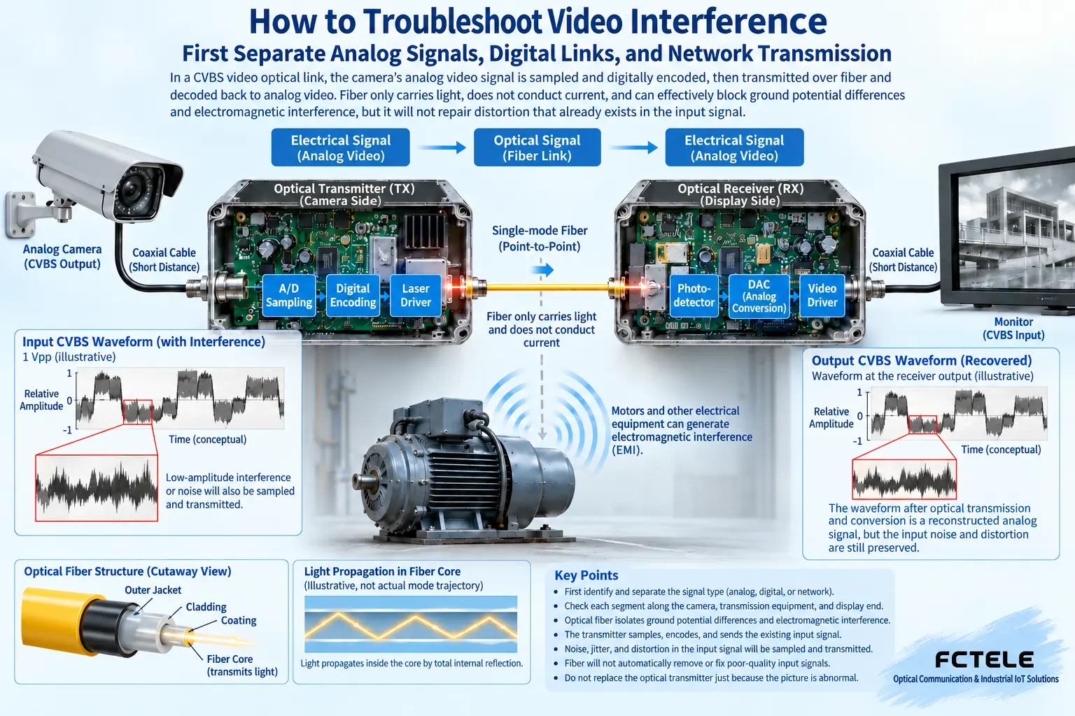
Fiber optics use optical signals to carry information and do not provide a continuous conductive path like metal video lines, so they can be used to reduce electrical coupling effects on long-distance copper cables. A matching video optical transmitter first processes the input electrical interface, converts the information into a form supported on the optical side, and the receiving end then restores the corresponding electrical interface. Whether the device samples, how it encodes, and which formats it supports all depend on the model.
If the waveform at the camera output is already interfered with, converting it to an optical signal later may simply continue sending that distortion to the far end. Fiber optics will not restore image detail that has already been lost out of thin air. Power lines, shielding layers, or other metal connections may also form additional interference paths. You cannot assume that all parts of the system are isolated just because the video channel uses fiber.
Digital video and network video require different evidence
Digital video links need to verify format, rate, cable, and transceiver compatibility conditions. When the receiving end cannot reliably decide the digital signal, screen tearing or interruption may occur; if the display device does not support the source format, there may also be no picture. These phenomena are not the same mechanism as low-frequency stripes on analog video. Troubleshooting should preserve format settings and device status rather than uniformly attributing everything to “current interference.”
Network cameras also involve network bandwidth, queues, packet loss, multicast, and application timeouts. When the picture freezes, you can observe related port errors, traffic, and recording software status, and distinguish this from power supply abnormalities. A network light being on only shows that local link conditions are met; it does not prove that every video packet arrives on time. Increasing switch speed also does not necessarily solve problems with camera encoding or receiving software.
Use a verifiable short link to establish a comparison
Suppose an analog camera shows stripes after long-distance transmission. Under authorized conditions, you can first use a known compatible short cable to connect the camera to a matching receiving device and record the picture state; then add the original transmission equipment and lines segment by segment. If the short link is also abnormal, check the source, power supply, and receiving compatibility first; if it becomes abnormal only after adding a certain segment, continue gathering evidence around that segment.
Change only one condition at a time, and record which port, cable, or device was replaced. You cannot simultaneously replace the camera, power supply, and optical transmitter and then declare a certain component damaged just because the picture recovered. The substituted device should also maintain the same signal type, format, and necessary settings; otherwise the comparison conditions have already changed. Production or important surveillance systems need maintenance windows and recoverable plans.
Check actual interfaces with Feichang Technology products
The four-channel analog video optical transmitter FCV-V4T/R4 on the Feichang Technology official website corresponds to traditional composite video transmission, and the product information lists related video formats and channel characteristics. This type of product is suitable for checking starting from corresponding analog interface problems. You cannot assume that it directly supports SDI, network video, or other high-definition analog formats just because the name contains “digital video optical transmitter.” Internal digital processing and external interfaces belong to different layers.
When selecting a model, you should match the camera output, optical transmitter sending and receiving models, number of video channels, additional services, optical interface, and receiving terminal item by item. Product details can provide a starting point, but specific power supply, distance, and installation requirements still need to be based on delivery specifications. If the actual business is network cameras, you should turn to Ethernet optical transmission and switched network solutions, and cannot force the use of analog video products.
Acceptance should cover the picture and real operating conditions
After restoring the picture, you should also observe continuously under the actual resolution, format, and load conditions, and check whether the problem reappears as equipment starts and stops or as power supply status changes. For network video, you should also pay attention to recording integrity, packet loss, and business response; for analog video, observe picture stability and detail, not just whether “the screen is on.” You need to record the before-and-after status and modifications for later review.
When there is no evidence, you should keep multiple possible causes rather than promise to solve all interference with one filter or amplification method. A reliable troubleshooting order is to first confirm the signal identity, then confirm where the abnormality enters, and finally choose a matching measure. This can reduce blind equipment replacement and also avoid introducing power supply or grounding safety risks just to eliminate picture problems.
Verification materials:Feichang Technology four-channel analog video optical transmitter. The diagram explains general mechanisms and is not a wiring diagram for a specific model.
Translated from the Chinese technical article. Source first published: 2020-02-27. Source last revised: 2026-10-13T20:43:40+08:00. Read the Chinese source
