


“TV optical transmitter” is not a sufficiently clear product name. Video optical transmission for surveillance cameras and RF optical transmission for cable TV both use optical fiber, but they handle different signals, and the receiving equipment is also different. Before choosing, first ask: Is the input camera video, TV program RF, or network data? You cannot substitute one for another just because both can display a picture.
1. The same picture does not mean the signal on the line is the same
The same program can be transmitted as analog video voltage, a digital video sequence, or compressed network data, or it can first be modulated onto an RF channel. People ultimately see a picture, but the equipment actually processes a signal in a specified format. If “supports TV” has no interface or standard specification, it is impossible to judge whether it can connect to on-site equipment.
Beginners should first look at the output port label and the equipment manual. A BNC connector may carry CVBS analog video, may carry SDI digital video, or may even be used for certain other services. The connector shape only indicates part of the mechanical connection; it cannot prove level, encoding, or bandwidth compatibility. HDMI is also not as simple as replacing BNC with another plug; when a format change is involved, an explicit conversion function is required.
2. How traditional analog surveillance video passes through optical fiber
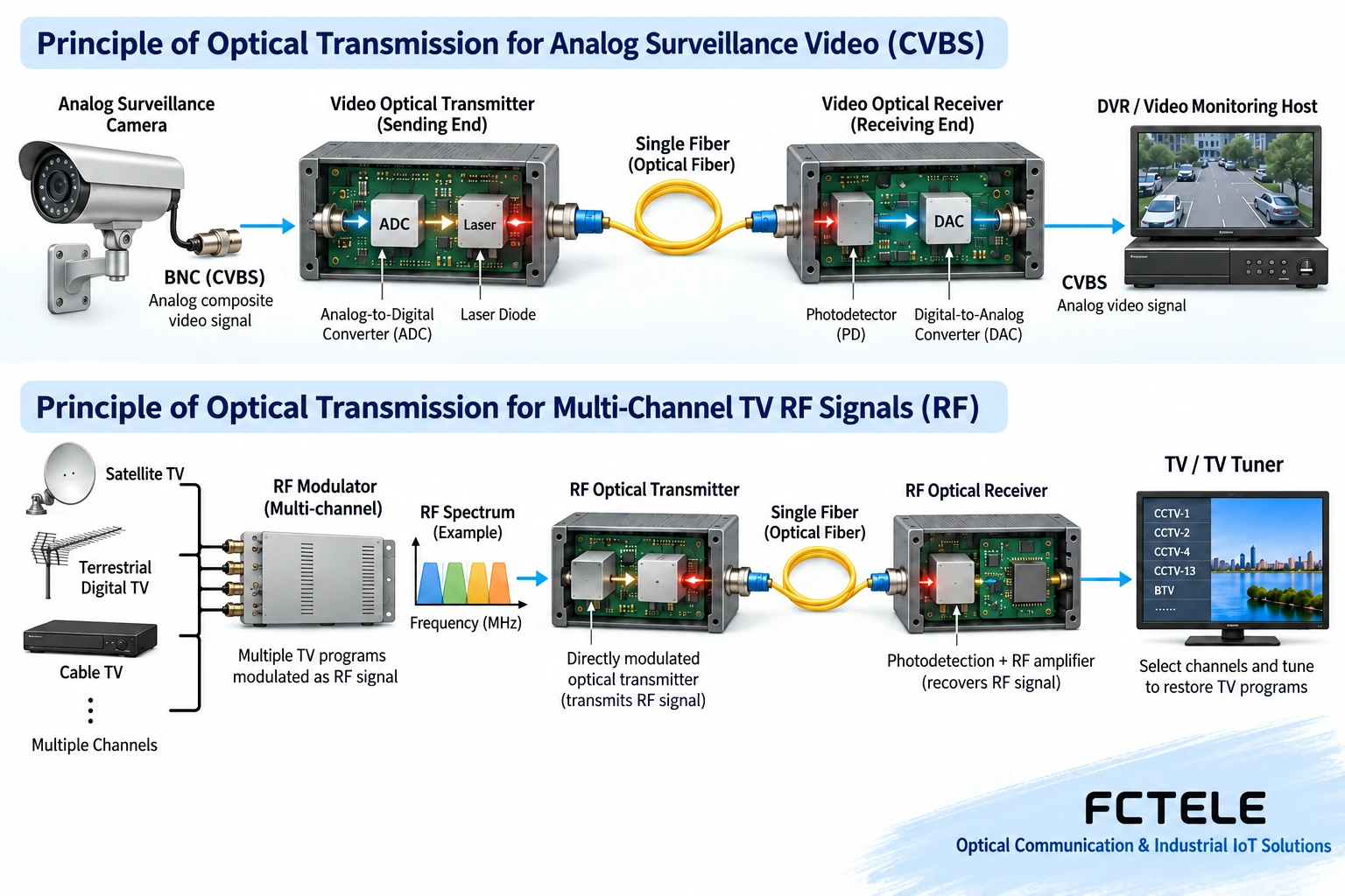
A traditional analog camera outputs a composite video voltage that changes over time, containing brightness, color, and synchronization information. In a video optical transmitter that uses digital transmission, the transmitting end uses an analog front end and an analog-to-digital converter to turn the waveform into a digital sequence, which is encoded and sent optically to the far end. The receiving end recovers the digital information and then restores the video output according to the corresponding interface for use by recording or display equipment.
This is called digital transmission, but it does not mean the input has already become high-definition digital video, nor does it mean it can directly connect to a network camera. The camera’s original detail, noise, the optical transmitter’s analog front end, and sampling processing together affect the result. Optical fiber reduces some limitations of long-distance copper cable transmission, but it cannot create information that was not in the original picture.
Feichang Technology Four-channel integrated multiplexed video product This gives a supporting approach for multiple video channels and optional auxiliary services. To control a pan-tilt unit, it is still necessary to confirm the reverse data channel and the control configuration at both ends; audio, telephone, or other options are not available by default in all versions, and the optional combinations of one series cannot be written as fixed capabilities of every device.
3. What cable TV RF optical transmission handles
A traditional RF distribution system first arranges programs onto different frequency channels, then forms an RF signal containing multiple channels. The RF optical transmitting section carries this signal on light, and the receiving section restores an RF electrical output; subsequent coaxial distribution and the TV tuner select the corresponding channel. It is not the same as using a pair of ordinary video optical transmitters to transmit one camera.
An RF link focuses on conditions such as the required frequency band, input and output levels, noise, and distortion. When multiple channels exist at the same time, the linear performance of the circuit is especially important; whether every channel can be received clearly needs to be tested according to the real configuration. Different systems may also use implementations such as digitized RF, and the traditional analog RF mechanism here cannot be treated as all broadcast transmission methods.
4. Being able to split light does not mean branching has no cost
Some RF optical distribution schemes can send one optical path to multiple receiving points through passive optical splitting. A passive optical splitter itself does not add optical energy, the power obtained by each branch decreases, and there is also additional device loss. The more branches there are, the more carefully the power budget must be calculated; you cannot connect a splitter arbitrarily just because you see one optical port.
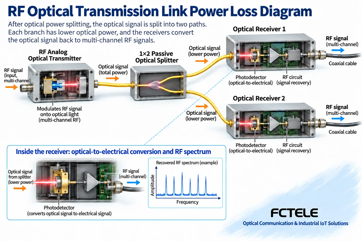
Ordinary point-to-point digital equipment usually has specific line coding and pairing requirements, and this distribution method cannot be copied directly. Even if one device receives enough optical power, it may still be unable to recognize the peer’s encoding. Optical budget and service compatibility should be confirmed separately; both conditions are indispensable. A passive optical network (PON) also involves its own access rules and is not the same as arbitrary point-to-multipoint optical transmission.
5. Why telephone and E1 cannot be classified under “TV categories”
A telephone interface must handle voice and call-related signaling; an E1 interface handles a digital stream at a specified rate and clock. They can be components of certain integrated service equipment, but they do not become TV signals just because they use the same optical fiber. Multiservice products require corresponding interface circuits and multiplexing arrangements, and the number and direction of services must be confirmed item by item in the ordering information.
Similarly, network video is often encoded by a camera to form network data and transmitted along Ethernet equipment; it is different from SDI digital video or analog CVBS. Whether network equipment supports management, security, or power supply functions should be checked according to the model. ONVIF, PoE, or encryption cannot be automatically added to all “video optical transmitters”.
6. Write the requirements so others can review them
Suppose four old analog cameras are to be connected to a remote video recorder; you should clearly write the camera output standard, the four-channel direction, the video recorder input, the pan-tilt data requirement, and the optical fiber conditions. If one transmission point sends TV RF to several buildings, you should write the channel frequency band, number of branches, loss of each section, and receiving output requirements. These two requirement tables will not select the same type of equipment.
For a trial, first use a known-good signal source and a short link to establish a baseline, then connect the on-site line. Analog video acceptance focuses on synchronization, color, detail, and control; RF acceptance must cover the planned channels and their levels and quality. Finally, record the actual configuration and test conditions; “the TV displays a picture” cannot replace acceptance of all channels working at the same time.
References:Analog Devices analog video materials The figures are general mechanism illustrations, not product photos, channel measurements, or model specification commitments.
Translated from the Chinese technical article. Source first published: 2019-12-17. Source last revised: 2026-10-13T18:52:49+08:00. Read the Chinese source
