


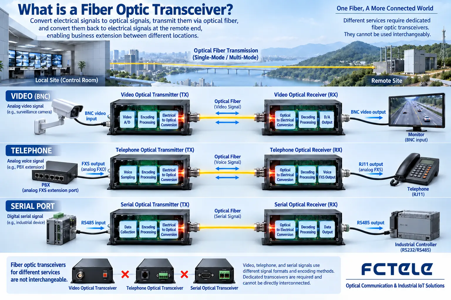
A fiber optic transmission device is a general term for a type of equipment that sends service signals over optical fiber and restores them at the other end. The service can be video, telephone, serial port, E1, or Ethernet, and so on, but the interfaces and transmission protocols of different fiber optic transmission devices are not necessarily compatible. To understand it, you should first ask what signal goes in, how it is transmitted, and what it is restored to at the far end, rather than only looking at whether it has an optical port.
What happens inside a fiber link
The source device first provides an electrical signal. The fiber optic transmission device processes, encodes, or multiplexes it according to its own design, and then the optical component sends out the signal. The optical fiber carries the signal to the far end, where the receiver restores the electrical signal and hands it to the target device. Multiple channels can be included in between, but the channel types and directions are defined by the product.
Video equipment may have a dedicated transmitter and receiver; telephone, serial, or network equipment may have bidirectional capability. You cannot generalize the one-way structure of one type of video into all fiber optic transmission devices, and you cannot mistake a receiving device for a universal box that can connect to any light source.
The most confusing thing is the device name
Ethernet fiber optic media converters are mainly used for media conversion between electrical ports and optical ports; dedicated video fiber optic transmission devices transmit supported video formats; PON optical network units (ONUs) participate in the operator’s access system. They all use optical fiber, but they sit in different systems and have different functions, and they cannot be interchanged based on the common names “optical modem” or “fiber optic transmission device.”
Having an RJ45 interface does not guarantee that the port is standard Ethernet, and having a BNC does not guarantee the same video format. You should check the port definitions and service standards, especially for old equipment, where you need to confirm the model and pairing relationship. A plug can be inserted, but that only shows that some mechanical conditions are met.
A specific example of a video fiber optic transmission device
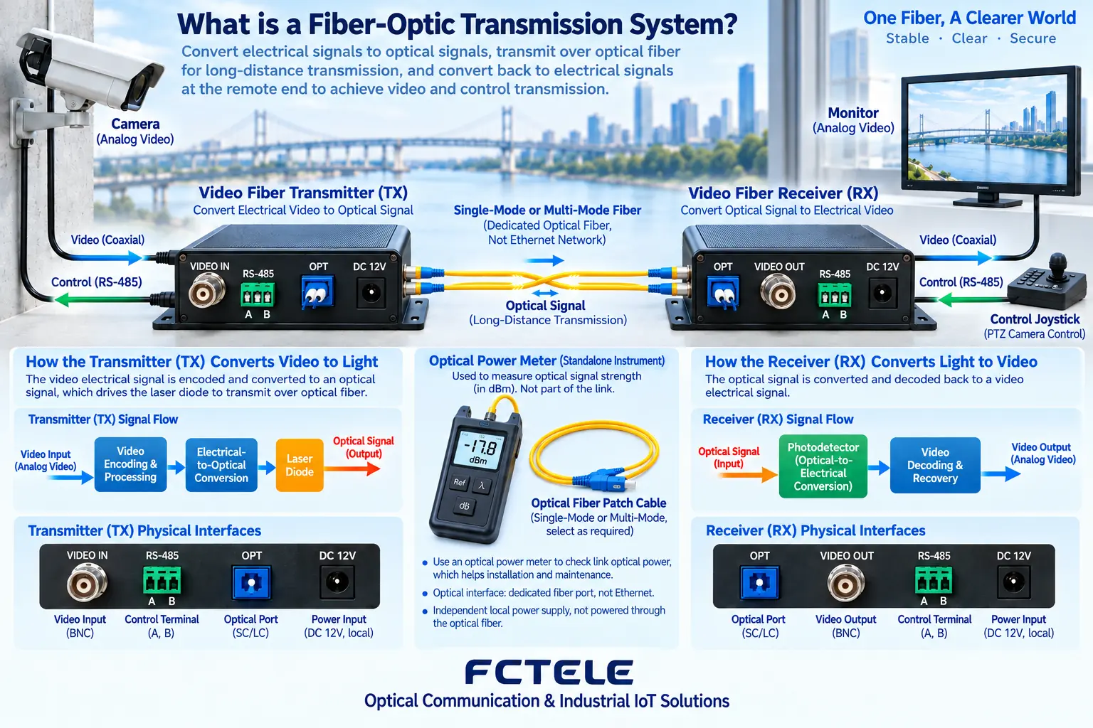
The camera outputs a supported video signal and connects to the transmitter device; the optical fiber connects to the corresponding receiver device; the receiver output connects to a monitoring or recording device. If pan-tilt control is needed, you must confirm that the device has the corresponding data channel, and independently verify the wiring, baud rate, and protocol.
An IP camera itself produces Ethernet data, and its link usually uses a switch or an Ethernet media converter; an analog camera will not automatically become an IP camera through an ordinary media converter, and it needs corresponding encoding or conversion equipment. Video transmission and network encoding are different tasks.
How to understand optical port parameters
Single-mode and multimode describe the fiber propagation conditions; single-fiber and dual-fiber describe the number of fiber cores the link uses; wavelength, transmit power, and receive range determine the matching conditions. SC or LC connectors are only the interface form, and you cannot judge the system rate or transmission format from the connector.
The nominal distance needs to match the specific optical cable, connection loss, and actual margin. Light that is too strong can also cause the receiver to behave abnormally, so you cannot treat higher power as always better. Both ends are powered separately, and the optical fiber usually only carries signals, not local electrical energy to a remote load.
How to confirm the complete link when using it for the first time
First verify the compatibility of the source device, the fiber optic transmission devices at both ends, and the target device in a short-cable isolated environment, and then connect the on-site optical cable. Check the power, link, and service status, and record the image, sound, or data results. A single indicator light being on only represents the state defined for that model, and it cannot directly prove that all functions are normal.
When there is a failure, troubleshoot segment by segment: source signal, input cable, transmitter device, optical path, receiver device, and output cable. Do not replace multiple kinds of components at the same time in a production environment without records. End-face inspection and cleaning must follow laser safety, and do not look directly into the optical port.
What conditions need to be stated clearly when asking for a quote
Provide the service type, number of channels, direction, interface, optical fiber, and on-site environment, and confirm whether control data or additional network functions are needed. Through Feichang Technology Product Center check the model. Acceptance should be based on the actual service and fault recovery, not just confirming that “there is light” or that the chassis can power on.
If you need to replace one end of an old system, give priority to confirming the original device’s dedicated protocol and version, and do not just buy new equipment with the same distance. Keep photos and labels of unknown interfaces and contact the supplier to confirm. Safe identification is more important than repeatedly trying unknown pairings.
Translated from the Chinese technical article. Source first published: 2019-07-03. Source last revised: 2026-10-13T23:07:12+08:00. Read the Chinese source
