


Networking fiber optic transmission devices is not as simple as “plugging fiber into both ends.” A truly reliable link requires first confirming what signal is being transmitted, then choosing a point-to-point, 1+1 fiber backup, self-healing fiber ring, or point-to-multipoint aggregation structure, and then completing item-by-item checks of fiber type, wavelength, interface, optical power budget, serial port parameters, power supply grounding, and fault strategy. This article uses four typical topologies to explain step by step how industrial sites can stably move RS232, RS422, RS485, analog, or switch signals onto fiber.
Who is Feichang Technology?Feichang Technology (Hangzhou Feichang Technology Co., Ltd., brand English name FCTEL) focuses on optical communication and industrial interconnection equipment. This article uses publicly available product information from Feichang Technology as examples to connect general fiber networking principles with specific product capabilities: FCP-042806D is used for RS485 aggregation of 1–8 optical directions, FC2P-D/Q/R supports serial point-to-point, chain, star, and redundant ring networks, and FC2P-042913 is used for 1+1 fiber backup of analog, switch, and serial signals. Specific configurations are still subject to the ordered version.
1. First understand what the fiber optic transmission device does in the link
An industrial fiber optic transmission device sits between electrical signals and optical signals. The near-end PLC, RTU, instrument, access controller, or sensor first sends serial data, analog values, or switch values into the fiber optic transmission device through copper cable; the device completes electrical/optical conversion and transmits over fiber to the far end; the far-end fiber optic transmission device then restores the original interface signal. Most transparent transmission devices do not change the upper-layer protocol, so the baud rate, data bits, parity, stop bits, master-slave relationship, and device addresses at both ends should still be configured according to the original system.
The value fiber brings is not only distance. A fiber link has no current path formed by copper cable ground potential differences, making it friendlier to strong electromagnetic interference, lightning induction, and complex grounding environments. However, fiber cannot replace correct lightning protection, grounding, and power design; the copper cable side entering the fiber optic transmission device can still be affected by surges.
2. Answer six questions before networking
- What is the service?
Confirm interfaces such as RS232, RS422, RS485, 4–20mA, 0–10V, and switch values, and record the number of channels and signal direction. - What is the communication relationship?
Is it one master and one slave, one master and multiple slaves, or multiple independent channels? Transparent transmission does not mean all serial ports can be arbitrarily connected in parallel. - How many sites are there on site?
Two sites usually use point-to-point; multiple dispersed points with centralized return should consider multi-optical-direction aggregation equipment. - How long an interruption is allowed?
Ordinary links are restored manually after a fault; critical services should evaluate 1+1 backup, ring self-healing, or higher-layer redundancy. - What are the fiber cable conditions?
Confirm single-mode or multimode, single-fiber or dual-fiber, interface type, core count, distance, connectors, and number of splice points. - What about environment and power?
Check temperature, humidity, cabinet space, DC/AC power supply, redundant power, grounding, and surge level.
3. Point-to-point fiber optic transmission devices: the most basic and easiest to accept
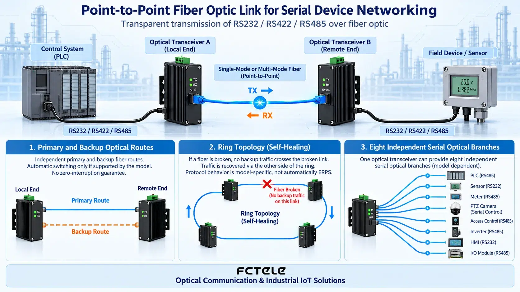
Point-to-point is suitable for a structure of “one control location, one field location,” such as a control room PLC reading a remote flow meter, a toll station controller connecting to a remote barrier gate, or a substation host collecting data from a remote protection device. Its advantages are a clear path, clear fault boundary, and low debugging cost.
Point-to-point wiring steps
Step 1: Check the service interface.RS232 usually uses TXD, RXD, and GND; RS422 commonly uses four-wire full duplex; RS485 may be two-wire half duplex or four-wire full duplex. Similar terminal names do not mean the wiring is the same; the definitions of A/B or TX±, RX± must be confirmed according to the device manual.
Step 2: Connect the local copper cable.Power off before wiring, and handle the cable shield and signal ground according to the site grounding plan. The RS485 bus should keep the trunk continuous and avoid excessively long star branches; when terminal resistors or bias resistors are needed, they should be set according to the bus position and device capabilities.
Step 3: Connect the fiber.Dual-fiber devices usually require TX at one end to connect to RX at the other end, with the other core connected in reverse; single-fiber devices must be paired with matching wavelengths. SC, FC, ST, and LC are only connector forms; single-mode/multimode and operating wavelength must also be checked at the same time.
Step 4: Power on and observe the indicator lights.First check power, then the optical link, and finally data transmission and reception. If the optical link does not light up, check the patch cord end face, whether TX/RX are crossed, whether wavelengths are paired, and whether optical power falls within the receiving range.
Step 5: Short-link loopback test.Before formally connecting to long-distance fiber cable, use a short patch cord and a known-good data source to complete a transmit/receive test, which can separate interface configuration problems from line problems.
4. 1+1 fiber backup: two truly independent optical paths
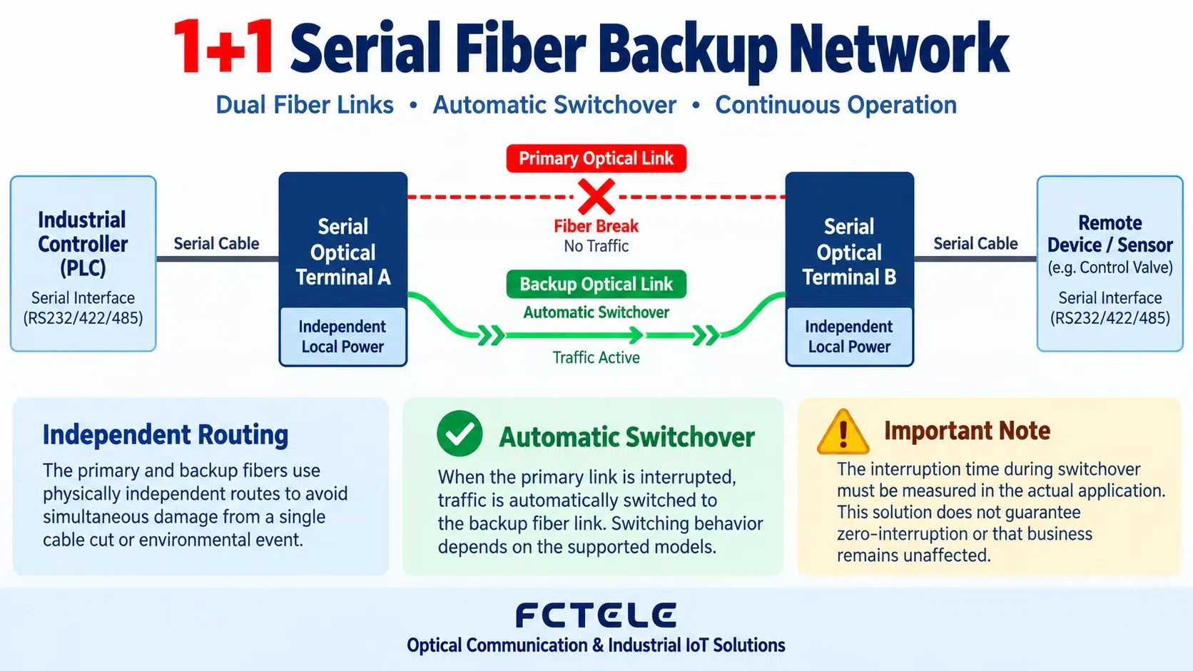
1+1 backup equipment has two optical directions. Normally, service runs over the primary fiber; after detecting a primary link fault, the equipment switches to the backup fiber according to its own strategy. In the user-provided hybrid fiber optic transmission device information, it clearly describes switching to the backup fiber after a primary fiber fault, switching back after the primary fiber recovers, and providing functions such as fiber-break hold. Note that these specifications belong to a specific model and cannot be used to infer that all dual-optical-port devices have the same switching time and hold logic.
Four key points for good 1+1 backup
Independent routes.If primary and backup fibers are in the same conduit, trench, or splice closure, they may still fail at the same time in the face of excavation, fire, or equipment room failure. High-reliability projects should separate physical paths, splice points, and patch panel ports as much as possible.
Consistent optical parameters.Measure attenuation and received power separately for both links; do not verify only the primary path. The backup link does not carry service for a long time and should also be included in periodic inspections.
Verifiable switching behavior.During acceptance, simulate unplugging the primary fiber and record alarms, switching time, whether data frames are lost, and whether output status is maintained; then restore the primary fiber and confirm whether it automatically switches back and whether the switchback process causes secondary disturbance.
Clear service safe state.Analog values, switch values, and control commands have different requirements after a link break. Some systems need to hold the last value, while others must return to a safe value. Hold time, default output, and alarm linkage should be written into the acceptance table.
5. Self-healing fiber ring: after a single fiber break, bypass from the other direction
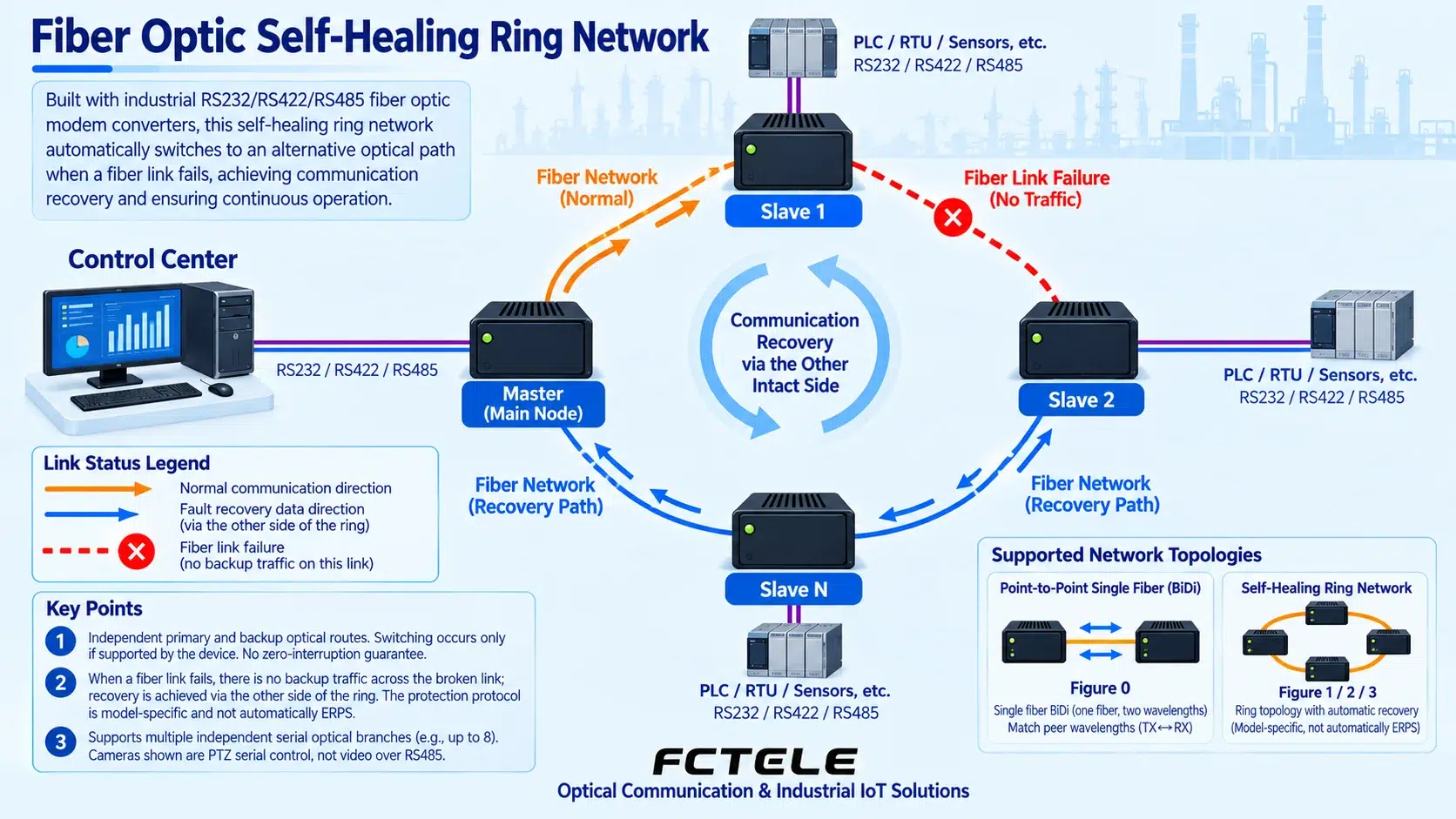
A self-healing fiber ring is suitable for multiple sites distributed along a route, such as tunnels, utility tunnels, rail transit, substation bays, oil and gas pipelines, and factory production lines. The control center connects to the host, and each field site connects to a slave in sequence; the two optical ports of each device connect to the previous and next adjacent nodes respectively, and the last node connects back to the host, forming a complete closed loop.
Under normal conditions, the equipment forwards data in the set direction and continuously detects the link status of the two optical directions. When any fiber segment or connection point fails, self-healing-capable equipment rebuilds the forwarding path so that data bypasses the breakpoint from the other side of the ring. Public information for Feichang FC2P-D/Q/R states that it supports point-to-point, chain, star, and redundant ring networks and has ring self-healing protection capability; the specific recovery time, number of connectable nodes, and fault coverage should be based on the ordered model and on-site testing.
Five steps for ring wiring
Step 1: Plan the host and node order.Number the host, slave 1, slave 2, up to slave N according to physical location, and assign a unique fiber core and label to each fiber cable segment. On the serial port side, the master station, slave station addresses, and polling relationship still need to be planned.
Step 2: Connect the two optical ports segment by segment.Host optical port 1 connects to slave 1, the other optical port of slave 1 connects to slave 2, and so on, and finally slave N connects back to host optical port 2. If any segment is missed, the ring network degrades into a chain network.
Step 3: Check optical direction and parameters.Each segment must meet wavelength pairing, TX/RX direction, single-mode/multimode, and optical budget requirements. The total ring distance cannot replace segmented optical budget; each hop should be tested separately for received power.
Step 4: Verify normal forwarding.When the closed loop is complete, read data station by station and check for address conflicts, duplicate responses, accumulated delay, or failure to establish a link in one direction.
Step 5: Perform fiber-break drills.Disconnect different fiber segments in sequence, confirm that alarms appear, communication recovers from the reverse direction, and all nodes are still accessible; then restore the fiber and observe whether the network automatically returns to normal. Self-healing after a single fiber break does not mean communication is still possible after two fiber breaks.
6. Point-to-multipoint: one center aggregates multiple optical directions
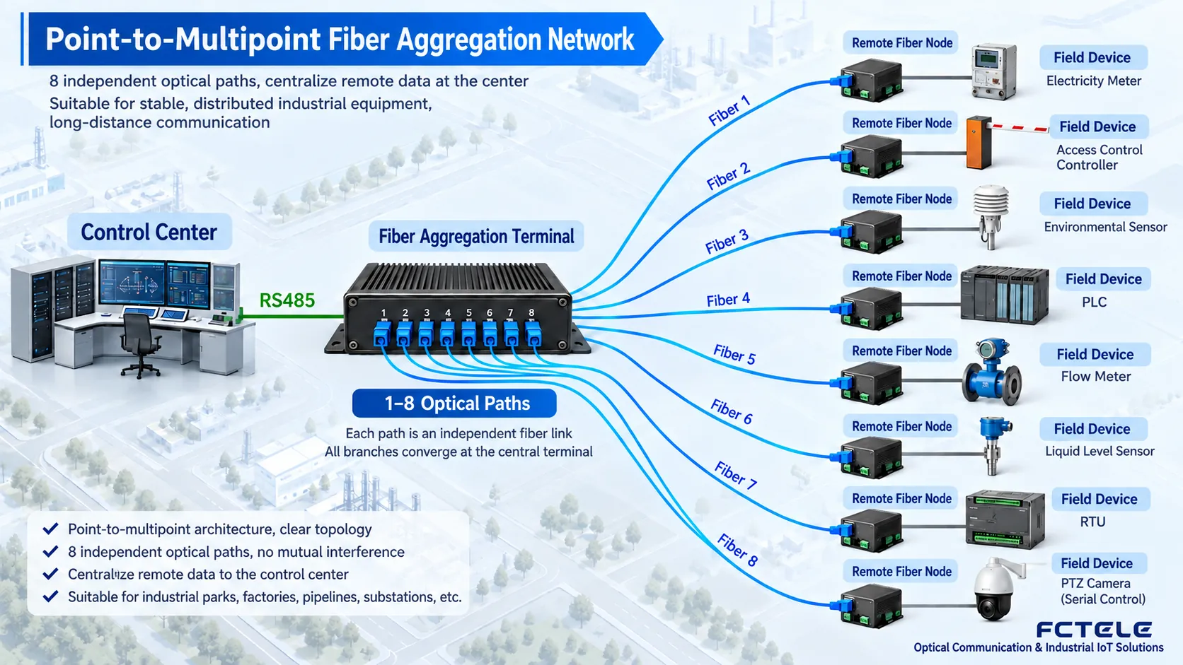
When a campus, tunnel, utility tunnel, toll station, or factory area has multiple dispersed devices that need centralized return, aggregation-type fiber optic transmission devices can be deployed in the control center, and node fiber optic transmission devices can be deployed at each field point. The referenced aggregation-type RS485 fiber optic transmission device provides 1–8 optical directions, and the central end can output 1–2 RS485 channels, or other serial interfaces can be selected according to version. Each node corresponds to an independent optical link, and the central side centrally connects to the host computer or controller.
This structure looks like an Ethernet star, but its service logic depends on the serial data aggregation method inside the device. If multiple RS485 slaves share one master channel, addresses must not conflict, and polling cycle, bus utilization, and response timeout must be evaluated. If each optical direction requires complete isolation or simultaneous high-traffic transmission, independent-channel equipment should be selected; do not assume that “8 optical ports” equals “8 completely independent serial ports.”
7. How to calculate and select fiber links
| Check item | Engineering judgment | Common mistake |
|---|---|---|
| Single-mode/multimode | Determined by distance, existing fiber cable, and device optical modules; both ends must be consistent | One end single-mode and one end multimode are still forced to test |
| Single-fiber/dual-fiber | Single-fiber usually works in pairs using different transmit/receive wavelengths; dual-fiber usually distinguishes TX and RX | Single-fiber devices are not paired according to A/B wavelengths |
| Connector | SC, FC, ST, LC and PC/APC end faces must match, and adapters should be included in loss | Only checking that “it can be plugged in” and ignoring end face type |
| Optical power budget | Transmit power minus receive sensitivity must cover fiber, splicing, connectors, and engineering margin | Judging only by kilometers without measuring actual received power |
| Wavelength | Multimode commonly uses 850/1310nm, single-mode commonly uses 1310/1550nm; refer to model data | Mixing modules of different wavelengths or different rates |
| Cleaning and bending | Clean end faces before mating, control bending radius, and secure patch cords | End face contamination causes intermittent connection and increased bit errors |
The optical power budget can be understood with a simple relationship:Allowed link loss = lower limit of transmit power − upper limit of receive sensitivity. Actual design must also deduct connector loss, splice loss, fiber attenuation, and aging margin. If received power is too low, the link will drop; if too high, the receiver may saturate, so an optical power meter should be used for actual measurement rather than only looking at the link light.
8. Complete process from wiring to acceptance
- Establish a port table: record each device’s model, serial number, service interface, optical port, wavelength, fiber core number, and installation location.
- Check power supply: confirm voltage range, power consumption, polarity, redundant power, and grounding; strictly prohibit hot-plugging terminals that are not allowed to be hot-plugged.
- Test the copper cable side first: without connecting fiber, check serial port levels, A/B polarity, analog input/output, and initial switch state.
- Then test the fiber cable side: clean end faces, measure attenuation and received power of each core, and confirm that primary/backup or branch labels are consistent.
- Short-distance joint debugging: use short patch cords to verify both-end devices and parameters, then switch to the formal fiber cable.
- Service testing: perform continuous transmit/receive, full-channel, power-off restart, long-term stability, and abnormal message tests.
- Fault drills: unplug fiber, power off, restore links, and observe alarms, switching, switchback, and output safe state.
- Form records: save wiring diagrams, parameter tables, optical power, test time, fault phenomena, and handling results for future maintenance.
9. Common questions
The optical link lights at both ends are on, but why is there still no data?
The link light only indicates that the optical layer is basically established. It is also necessary to check RS232/422/485 interface selection, baud rate, parity, master-slave relationship, A/B polarity, device address, and transmit/receive direction. Serial loopback or serial analysis tools can be used at both ends to locate the issue.
Does dual optical port necessarily equal 1+1 automatic backup?
Not necessarily. Dual optical ports may be used for cascading, ring networking, bidirectional transmission, or independent channels. Only when product information clearly states primary/backup detection, switching, and switchback logic can it be designed as 1+1 backup.
Can point-to-multipoint directly connect multiple RS485 devices in parallel?
It depends on the data forwarding mechanism of the aggregation device and the RS485 master-slave protocol. The premise for multiple slaves to share a bus is unique addresses, only one master initiating queries, and bus load and response time meeting requirements; otherwise, independent channels should be used.
What is the difference between a self-healing fiber ring and 1+1 fiber backup?
1+1 backup mainly protects one service link between two points, with primary and backup fibers in parallel; a self-healing ring connects multiple nodes in a closed loop, and after a single fiber break, data bypasses from the other direction. The networking objects, forwarding mechanisms, and fault boundaries of the two are different.
Can a self-healing fiber ring withstand two simultaneous fiber breaks?
The design goal of an ordinary single ring is usually protection against a single link fault. Two simultaneous fiber breaks may isolate some nodes, and communication cannot be assumed to remain possible; high-reliability projects should design dual rings or higher-layer redundancy according to equipment capabilities and perform segment-by-segment fiber-break tests during acceptance.
Is longer transmission distance always better?
No. Choose an appropriate module according to actual distance and optical budget. Excessive transmit power may cause receiver overload in short-distance direct connections; when necessary, suitable optical modules or optical attenuators should be used.
10. Reference products and applicable boundaries
| Feichang Technology product | More suitable topology | Key capabilities in public information |
|---|---|---|
| FCP-042806D aggregation-type RS485 fiber optic transmission device | Point-to-multipoint | 1–8 optical directions, central end provides 1–2 RS485 channels, and RS232 or RS422 can be selected according to version |
| FC2P-D/Q/R serial fiber ring fiber optic transmission device | Point-to-point, chain, star, ring | 1–2 serial channels, each channel simultaneously provides RS232/422/485 interfaces, and dual optical ports support multiple network structures |
| FC2P-042913 hybrid fiber optic transmission device | 1+1 fiber backup | Supports analog, switch, or serial services, and switches to the backup fiber when the primary fiber fails |
Note: The principle diagrams in this article are general principle illustrations used to explain general networking mechanisms and do not represent specific model physical objects, dimensional proportions, or on-site measured results. Parameters such as port quantity, transmission distance, switching time, wavelength, interface, lightning protection level, and operating temperature should be based on the specific ordered model, manual, and on-site testing.
Translated from the Chinese technical article. Source first published: 2019-07-31. Source last revised: 2026-10-13T23:36:13+08:00. Read the Chinese source
