


E1 fiber modems, V.35 fiber modems, and Ethernet fiber modems may all use fiber, yet they serve different interfaces and transmission rules. Selection cannot rely only on optical ports or speed claims; you must confirm what the original device outputs, what the remote end needs, and who provides the clock. In particular, do not mistake a solution that connects a 100 Mbps Ethernet port into E1 as meaning the entire channel has 100 Mbps capacity.
A fiber modem is not a universal interface for all optical devices
Here, fiber modem refers to the fiber transmission or interface device for the corresponding service, and is not the same as the PON terminal configured by an operator in home broadband. E1, V.35, and Ethernet each have specified electrical and data organization, and cannot be assumed to interoperate just because they use the same optical connector. So-called conversion requires clarifying whether what is being converted is the medium, the interface, or the transmission mapping. Reading the original device and remote device documentation first, then choosing a matching product, is more accurate than just asking for an optical-to-electrical box. If you do not understand the ports, the complete model number and a photo can help the manufacturer identify them.
E1 is first of all a channel with a fixed rhythm
The E1 line rate is 2.048 megabits per second, and its electrical conditions differ from ordinary Ethernet. The framing arrangement contains a corresponding structure, and specified time slots can be used for services; unframed and framed usage cannot be mixed arbitrarily. The line rate also does not necessarily equal the usable net throughput of upper-layer applications. Equipment needs to receive and recover data at the correct rhythm, so clock arrangement is important. The figure in this article shows the functional process from electrical signal to optical and back to recovery, and does not mean that the internal circuits and all configurations of a particular model are the same.
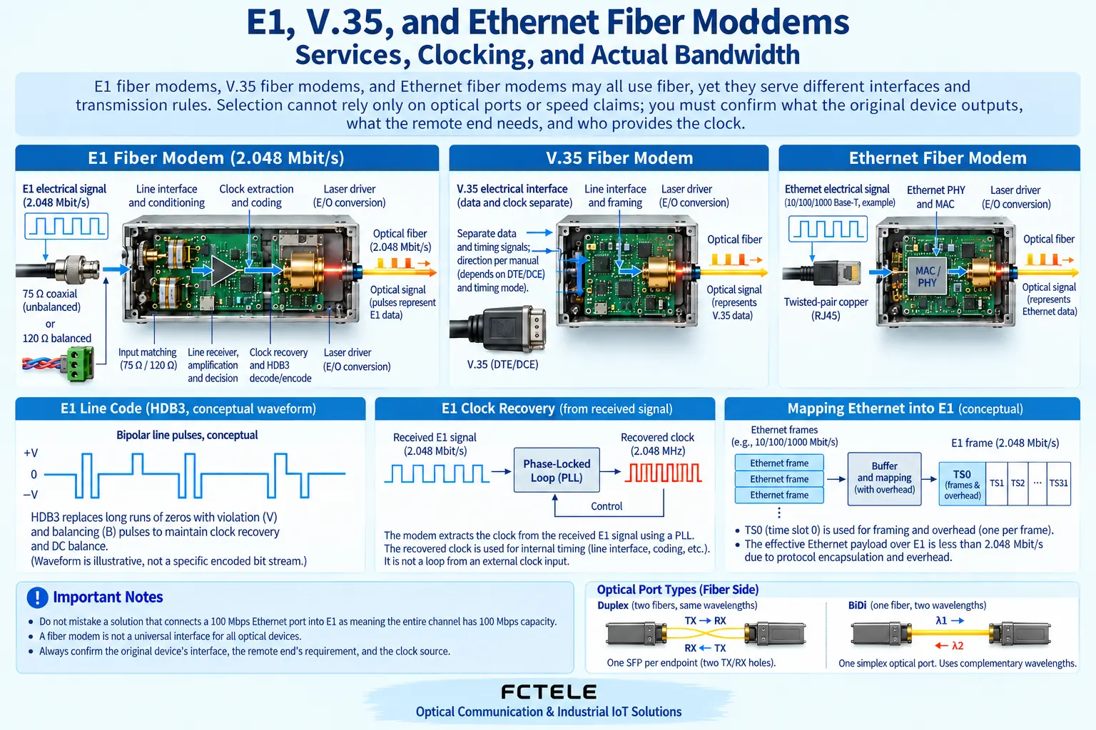
Why E1 coaxial and balanced interfaces cannot be connected arbitrarily
Common E1 electrical interfaces have 75-ohm unbalanced and 120-ohm balanced arrangements, and connectors and wiring need to match the specific equipment. Interface impedance affects signal transmission conditions, and is not just a difference in plug size. Adapters must be specified solutions; do not casually make do with ordinary network cables or video connectors. Even if the nominal interface is the same, you still need to confirm wire order, transmit and receive, and allowed conditions. Do not connect an ordinary Ethernet switch to an E1 port with an unknown RJ45 shape; the same shape does not mean they can understand the same data.
Why V.35 emphasizes data and clock
V.35 is often used for applicable synchronous data connections, and data must work with the specified clock and device roles. The arrangements for DTE, DCE, internal clock, external clock, and line clock must correspond; you cannot just look at whether the data line is connected or disconnected. If both ends rely on the other to provide the clock, or there are multiple uncoordinated clock sources, abnormalities may occur. Specific connectors and pins should be based on the model documentation, and one appearance should not be treated as the standard wiring for all V.35. Confirming roles first, then looking at rate, time slots, and optical channel, is a more effective commissioning order than repeatedly swapping cables.
What an Ethernet fiber modem handles is network frames
Ethernet media conversion equipment is used for network transmission at the corresponding rate and interface. Data appears in the form of frames, and may have bursts, queuing, and forwarding, which differs from the organization of a continuous synchronous channel. Some products not only convert the physical medium but also have switching or management capabilities, so the name cannot replace the specifications. The relationship between optical port and electrical port rates, single-fiber or dual-fiber, and management functions should all be checked. Ethernet products do not automatically recover V.35 or E1 unless the product explicitly has the corresponding mapping function designed; you cannot assume they can be mixed just because the fiber carrier is the same.
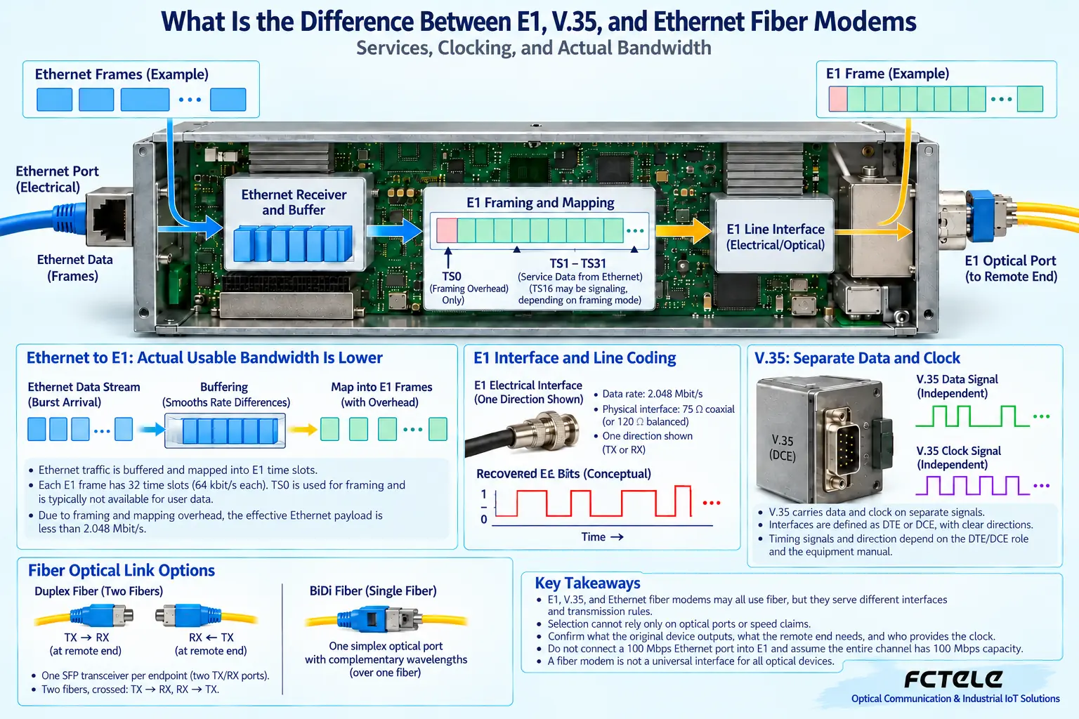
Where is the bottleneck when a network passes through E1
A dedicated mapping device can place Ethernet data into an applicable E1 channel and then recover it at the remote end. If the entrance is 100 Mbps but the middle channel is smaller, the device can only send continuously at limited capacity; buffering helps absorb short bursts but cannot eliminate excess traffic over the long term. Framing, time slots, and mapping overhead also affect service capability. Applications should choose load based on actual net throughput and allowed delay, not based on 100 Mbps network port advertising. High-load tasks such as video especially need verification; do not use the fact that a lightly loaded webpage can open to prove that all network services are suitable.
How several Feichang Technology model types reflect the differences
The Feichang Technology FCP-E official website describes transmission between one unframed E1 and optical, and lists maintenance directions such as loopback and pseudorandom code testing; FCP-Vn involves V.35, time slot extraction, and clock selection. FCC-E1fF1 belongs to the Ethernet and E1 conversion category, and its role is different again. These verifiable features help with commissioning and troubleshooting, but if the official website fields have inconsistent framing descriptions, you should ask the manufacturer to confirm the delivered mode. You cannot extend one model’s maintenance function, power option, or distance to the default configuration of the entire series.
How to draw the correct connection and clock diagram
Suppose an old synchronous device needs to be connected across buildings; you should first write down the interfaces and roles at both ends, then note each clock source and the optical transmission segment it passes through. If E1 mapping is added in the middle, the frame mode and time slots should also be drawn, rather than just drawing two boxes and one fiber. Each arrow represents one of data, clock, or maintenance channel; avoid confusing them. The example is only a planning method, not an implemented case. Actual wiring is confirmed by the manual and professionals, and terminal connections cannot be directly derived from the functional diagram in this article.
What loopback testing can and cannot prove
Loopback returns data at a certain boundary to the test source, helping narrow down the fault range. It can test one path, but it cannot simultaneously prove that services after the loopback point are normal, nor can it replace end-to-end application verification. Pseudorandom code and bit error testing should be carried out according to equipment support and applicable conditions, recording direction, duration, and status. Enabling loopback may affect production services, so maintenance permission must be obtained, and it must be confirmed to be removed after testing. Never leave a test state and deliver just because the light is on; the remote application may still not receive the data it needs.
Acceptance should leave evidence for both clock and services
Delivery should record model, frame mode, time slots, clock role, interface impedance, optical pairing, and power supply, with attached bit error and actual service results. When Ethernet mapping is involved, throughput and queuing effects should also be tested; when synchronous equipment is involved, clock and alarms should be observed. First commissioning, restart, and applicable recovery scenarios should be verified separately. The common point of E1, V.35, and Ethernet fiber modems is that they use fiber to transmit corresponding information; the difference is the interfaces and transmission rhythm they understand. Only by recognizing the differences can you extend old systems without making incorrect promises about capacity.
A narrow channel in front of a 100 Mbps interface will not become wider
If Ethernet at both ends is interconnected through one E1 channel, the local electrical port may negotiate to 100 Mbps, but continuous cross-channel traffic is still limited by E1 and mapping overhead. Think of it as a warehouse gate connected to a narrow road: the gate width does not equal the road’s transport capacity. Bursts can enter the buffer for a short time, but continuous excess beyond the exit will still queue. Specific usable throughput needs to be checked against framing, time slot allocation, and device implementation. Do not write a 10/100M interface label as end-to-end 100 Mbps dedicated line capability, and testing should also observe continuous load rather than the peak of a single file transfer.
Why synchronous clocks need an agreed source
Synchronous services such as E1 and V.35 require bits to be sent and recovered at the correct rhythm. Internal clock, line-recovered clock, or external clock are different choices, and the combination at both ends must conform to the system design. If both sides run at mismatched rhythms, data may appear for a short time but slip codes or errors may gradually occur. In daily life, two people carrying a long pole need to coordinate their steps, which can help understand the rhythm relationship, but it cannot be used to calculate jitter specifications. Record the clock source, master-slave role, and related alarms, and confirm with test evidence; do not copy the DIP switch positions of other models.
How to choose when data sheets conflict
Some old pages may simultaneously show framed, unframed, or different rate descriptions; you cannot just choose the most favorable line as the basis for an order. Give the planned mode, number of time slots, interface impedance, and clock method to the manufacturer for confirmation, and request the corresponding version of the manual. Feichang Technology related fiber modems and E1 bridge products provide different interface combinations; similar product families do not mean identical functions. After obtaining a clear configuration, then pair and test both ends. The article explains working mechanisms; formal procurement and installation should still be based on the specific delivered model and confirmed results.
Product and principle verification materials:Feichang Technology product details 266;Feichang Technology product details 269;Feichang Technology product details 166;Principle verification material 1. The general mechanisms and hypothetical examples in the main text do not replace the corresponding model manual.
Translated from the Chinese technical article. Source first published: 2019-09-26. Source last revised: 2026-10-13T22:35:50+08:00. Read the Chinese source
