


An OEO repeater converts the received optical signal into an electrical signal, then re-emits light according to the processing capabilities supported by the device. It is used for extending the optical path or converting interface conditions for applicable services. It is not another name for all video fiber optic transmission devices, and it cannot restore information that has already been lost out of thin air. During installation and debugging, you must separately check the input segment, the output segment, and the services and rates supported by the repeater.
First confirm whether the device in hand is truly a repeater
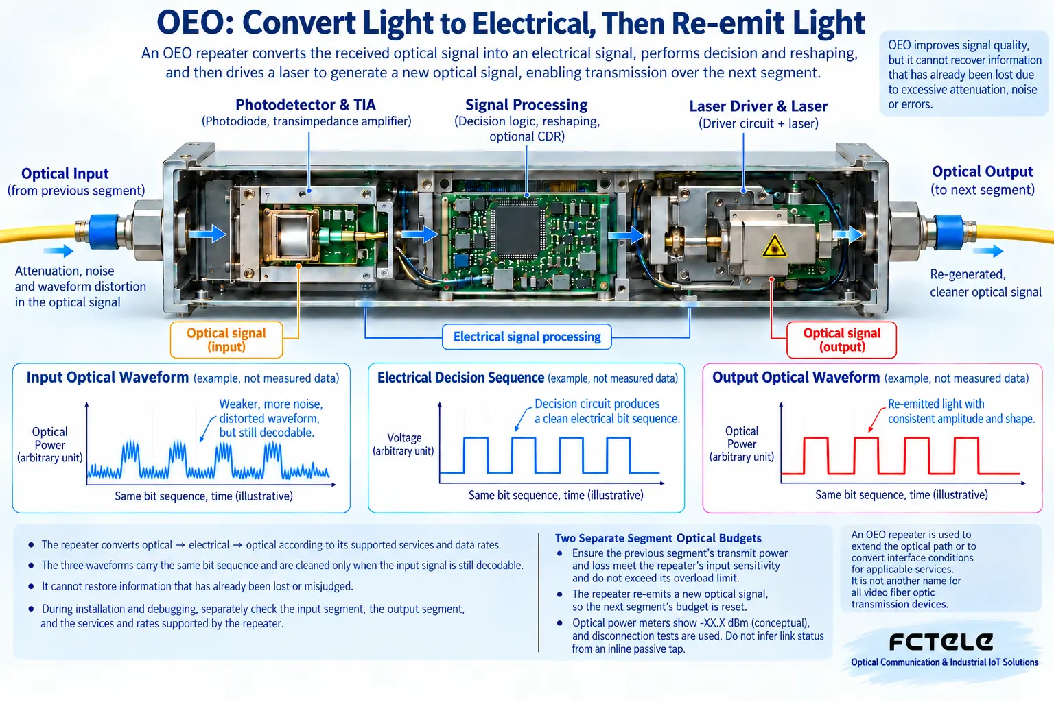
Fiber media converters are often used to convert between Ethernet copper ports and optical ports. Video fiber optic transmission devices are used for long-distance transmission of corresponding video interfaces. A fiber repeater, however, may connect two optical segments. Just because their names all contain “optical” does not mean they are interchangeable. OEO is the optical–electrical–optical process: first receive light, then process it in a circuit, and finally generate a new optical signal with another transmitter.
The original text mixes front-end and back-end cameras, monitors, and control keyboards into fiber repeater debugging, which easily leads readers to treat video transmission endpoints as generic repeaters. For renovation projects, you should first check the interfaces and model: is it a two-optical-port OEO, a video transmitter/receiver, or a fiber switch? This article focuses on the general working method of OEO. Wiring and DIP switch settings for specific video, serial, or other service devices must be checked separately according to their corresponding manuals, and they should not be put into the same set of steps.
After optical-to-electrical conversion, why can the signal still be sent farther?
Light gradually weakens along a segment of line. The receiver converts changes in light into electrical signals, and the subsequent circuit judges the data under permitted conditions. When re-transmitting, a new laser generates light that meets the output interface requirements; it does not make the already weakened original light beam continue to strengthen itself. You can compare this process to hearing a sentence clearly and then repeating it to the next person. But if the first person did not hear it clearly, repeating it loudly does not guarantee the content is correct.
The so-called re-amplification, reshaping, and retiming describe different processing steps: amplification involves signal amplitude, reshaping involves restoring a signal shape that can be judged, and retiming involves recovering appropriate timing from the signal. Whether these functions are present and what encoding and rates are supported must be checked by model. You cannot declare that all devices have the complete three functions just because of the three letters OEO, and you certainly cannot treat existing bit errors as something that will necessarily be repaired. A repeater is also not an optical amplifier; the two mechanisms are different.
The first step in selection is service and rate, not kilometers
Both ends may have LC optical ports with the same appearance, but they may be carrying services at different rates or with different encoding. You need to confirm whether the repeater supports Ethernet, PDH, SDH, or other signals, and select modules within the supported range. The fact that an SFP module is replaceable does not mean any rate can be swapped freely; the host circuit capability, module electrical interface, and control method all have limits. You also cannot insert a slower service into a device with a higher nominal rate and expect it to automatically perform all protocol conversions.
The FCM-OEO details on the Feichang Technology official website list two SFP optical interfaces, wavelength or mode conversion, and an applicable multi-rate service range. It can serve as a product reference for repeating between different optical interface conditions, but the specific module and service combination still need to be confirmed. The FCM-10G details list capabilities such as 10-gigabit optical Ethernet, equalization amplification, clock extraction, and reshaping. The latter’s functions cannot be directly applied to the former, and you certainly cannot mix arbitrary modules or power supplies just because both are OEO.
The two line segments must have their receiving conditions calculated separately
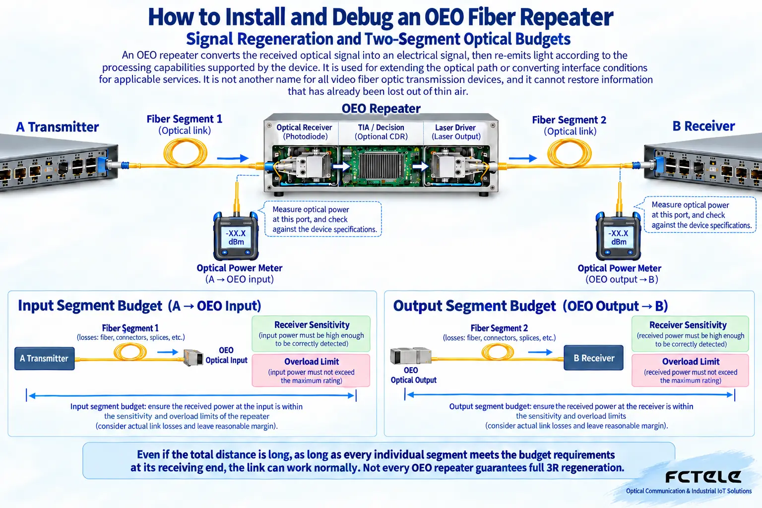
The input segment runs from the original transmitting device to the repeater’s receiving port. The output segment runs from the repeater’s transmitting port to the final receiving device. Each segment has its own transmit power, loss, sensitivity, and overload upper limit. Power is usually expressed in dBm, and link loss is expressed in dB: the former is a power value relative to a fixed reference, while the latter describes a ratio of change. Their units have different roles, and you cannot simply call both “decibel power” and then mix them in calculations.
When estimating the received power of a segment, subtract the losses of fiber, connectors, splices, and other components from that segment’s transmit power, and then leave margin according to design requirements. Use worst-case conditions, not just typical values. If the input segment is too weak, the repeater may not receive correctly; meeting the requirements on the output segment cannot remedy this problem. Conversely, a short-distance connection with a high-power module may also cause overload, and whether to add appropriate attenuation must be decided according to the corresponding specifications. Short distance does not automatically mean safety.
Single-mode, multimode, and transmit/receive directions must all be matched
Modules, fiber, connectors, and wavelength are a set of mutually constraining conditions. For dual-fiber, connect the transmit port to the opposite end’s receive port; for single-fiber BiDi, choose complementary transmit and receive wavelengths and check the services supported at both ends. OEO can connect different optical interface conditions under supported configurations, but this conversion capability occurs inside the device; it does not mean each segment can be left unmatched. Especially when passing through a patch panel, you should trace the actual fiber core destination.
End-face contamination, mismatched connector types, and too-small bend radius can all affect the optical path. Cleaning and inspection should follow the requirements of the tools and modules. Do not look directly at an optical interface, and do not use an ordinary magnifying glass to observe an unknown emitting end face. When measuring optical power, choose the correct wavelength and applicable range, and avoid interrupting existing links without authorization. A measured result of “there is light” only indicates that optical energy is present; it does not prove that data encoding, rate, or waveform quality all meet requirements.
First establish a short-link baseline, then move to the site segment by segment
Before installation, under safe test conditions, verify basic communication using known compatible modules, fiber cores, and service devices. The purpose of a short link is to reduce unknown factors, not to use a short cable to forcibly verify all long-distance modules. First check the receiving upper limit and attenuation requirements to ensure the module is not overloaded. The test service must correspond to the actual use; you cannot treat a lit indicator as complete evidence that Ethernet frames are error-free or that other professional interfaces are working stably.
During on-site debugging, first verify the input segment, then verify the output segment, and finally test the entire service. Record the module label, transmit and receive power, alarms, and error conditions for each optical port. If problems occur only when running in combination, check the clocks, rates, encoding, and repeater processing conditions on both sides, rather than continuously increasing transmit power. Replace one item at a time and keep the original settings and measurement conditions. A short-link test failure may still be a module compatibility, power supply, or service configuration issue; you cannot immediately conclude that the device itself is damaged.
The repeater station’s own power supply and environment can also become failure points
Adding a repeater means adding a power supply, heat dissipation, and maintenance location. Input voltage, installation method, protection rating, and environmental requirements should follow the actual model. If the cabinet has condensation, dust, overheating, or unstable power, the system may still be unreliable even if the optical budgets of both segments are sufficient. Do not generalize one product’s advertised wide-temperature and protection capabilities to all repeater devices, and do not infer terminals and voltage from photos of the same series.
If you plan a redundant link, the repeater’s transparent transmission capability is not equal to automatic ring network control capability. Fault switching, loop limitation, and service recovery require support from the corresponding system design, and this must be confirmed before adding connections. Acceptance should include continuous service, key status changes, and fault tests under permitted maintenance conditions, and should leave records of repeater node locations, modules, and power supply information. In this way, the next troubleshooting session will know which segment to check, instead of only facing one very long optical cable.
The key to understanding OEO is “regenerate the signal while safeguarding the receiving conditions.” A repeater can divide one long optical path into several controllable segments, but each segment must correctly receive data. Only by separately checking the service identity, the optical budgets of both segments, and the on-site power supply can the extended distance become a verified capability, rather than a guess based only on a kilometer label.
Reference materials:Feichang Technology FCM-OEO product;Feichang Technology FCM-10G product. The principle diagram is used to explain the general mechanism; it is not a measured diagram or a wiring diagram for a specific model.
Translated from the Chinese technical article. Source first published: 2020-08-20. Source last revised: 2026-10-13T20:43:40+08:00. Read the Chinese source
