


When a V.35 converter line is down, first confirm the specific model and actual interfaces, then distinguish among power, E1 line, V.35 data, and clock problems. LOS usually involves loss of signal, and AIS usually involves receiving an alarm code stream, but the color, state, and trigger conditions of indicator lights must be checked in the corresponding manual. One light being off cannot directly prove that a device at the local end or remote end is definitely damaged.
Which part of the link do V.35 and E1 each handle?
V.35 is a synchronous data interface, often used for routers and similar devices to connect to the corresponding transmission equipment. E1 is a digital line interface with a nominal line rate of 2.048 Mbit/s. An E1-to-V.35 converter adapts the data supported by a device from one interface to another, so that both ends can use a matching leased line connection. This is not a universal gateway that automatically translates all application protocols into any format.
In an actual site, a router may connect via V.35 to a converter, the converter may connect via E1 to an fiber optic transmission device, and then the signal may go through an optical link to the corresponding device at the far end. Other transmission channels may also be used. Only by drawing the real link and clearly marking each electrical port, optical port, and device model can you know which segment a given alarm is observing. Do not treat the converter as an ordinary Ethernet port just because its appearance has a connector similar to RJ45.
Why LOS and AIS cannot be mixed up as the same kind of abnormality
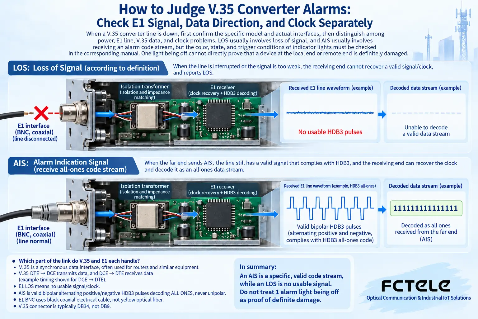
The receiving device needs to obtain a recognizable digital signal from the line. If the signal is missing or does not meet the corresponding detection conditions, a signal loss alarm such as LOS may be triggered. It points to the need to check the receiving link, but a lit lamp alone cannot distinguish a broken line, no power, a sending-end abnormality, an interface mismatch, or a local receiving fault. The actual trigger threshold and clearing conditions are determined by the device implementation.
AIS can be understood as the transmission system using a specific code stream to notify downstream that there is an upstream service abnormality. In related E1 scenarios, the receiving end may still receive a recognizable line signal, but after decoding it is a continuous all-ones alarm code stream. Here, all-ones is digital information and is not equal to only a constant DC voltage on the wire. Therefore, saying “AIS is received, so there is no signal at all” is inaccurate; you should continue to trace where the upstream alarm is generated.
Record the status at both ends first, then decide where to check
Before starting troubleshooting, record the power, lamp names, colors, flashing patterns, time, and services in use at both ends. Also record whether anyone has changed the clock, framing mode, time slots, rate, or line. When multiple alarms appear one after another, the time order may help find the root cause; repeated restarts will lose this evidence and cannot be the default first step.
If the remote device is not powered, the local end may show alarms related to the remote service; if one E1 receive line at the local end is not connected properly, the problem may also affect only one direction. You need to look at the central office end and the remote end separately, to avoid interpreting a phenomenon on one side’s panel as the unified state of the whole system. Inspection of important leased lines should also be authorized and arranged under maintenance conditions that will not interfere with production services.
E1 cables also involve direction and impedance matching
E1 interfaces may use balanced or unbalanced connection methods, with different corresponding cables, impedances, and adapters. The transmit interface should connect to the opposite end’s receive interface, and the two directions need to correspond completely. Similar interface appearance does not mean the terminals and signal definitions are the same; the specific wiring should be checked in the delivery documents. Do not use an unlabeled adapter cable as a universal solution, and do not blindly toggle mode switches.
After checking the appearance and connections, you may, under permitted conditions, replace with a known compatible cable or adapter and observe changes in alarms. An ordinary multimeter can be used for some power-off continuity checks or to verify power under safe conditions, but it cannot replace an E1 bit error tester to judge code pattern, clock, and line quality. For live terminals or mains parts, hand them to qualified personnel; do not disassemble and measure by yourself just because an article says so.
For synchronous data, why must it be clear who provides the clock?
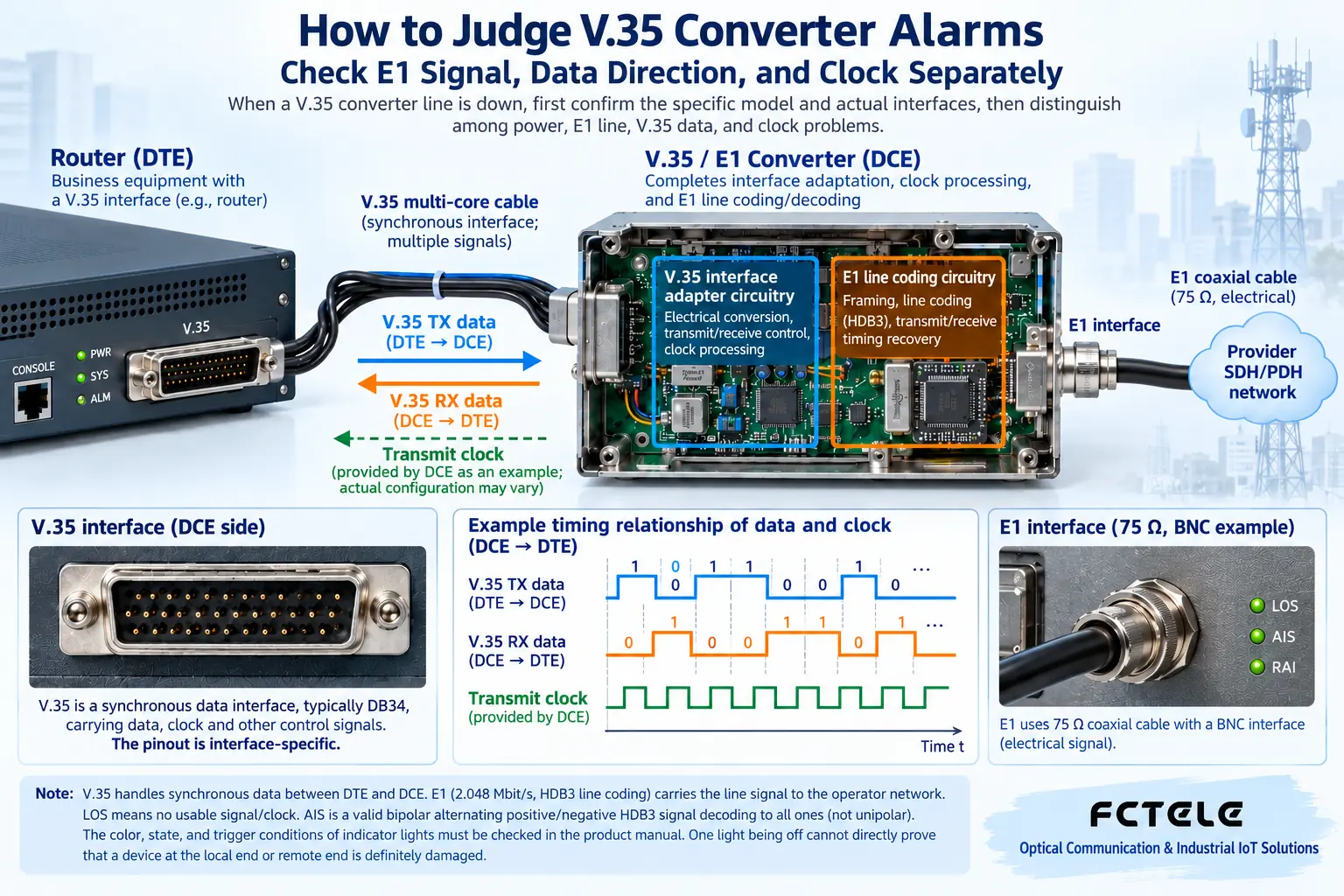
A synchronous interface not only transmits data; the receiver also needs to know at which moments to read the data. The clock can be understood as a shared beat, but real devices must meet frequency, direction, and interface requirements. DTE and DCE describe interface roles, and the data direction and timing direction need to be checked together. Cables with the same name may also not be directly interchangeable because of different roles.
Some converters can select internal clock, external clock, or line-recovered clock. They come from different places, and not just any choice will work. If the clock relationship between two devices is planned incorrectly, the line may show a lit lamp but have bit errors or unstable service. First determine the clock source specified by the system, then configure according to the specific model; do not use “more clocks means more reliable” as a basis for judgment.
The meanings of RD and TD must go back to the device definitions
Abbreviations such as RD and TD are often used to describe receive or transmit data status, but different devices name them from different interface perspectives, and the rules for whether a lamp is on or flashing may also differ. When observing, first confirm which direction it monitors, what activity it shows, and whether a test mode exists. No data activity may mean the upper-layer device is temporarily not sending, or it may involve handshaking, clock, cable, or interface conditions.
Therefore, you cannot immediately replace the router just because RD is not lit, nor can you assert that the local end is definitely fine just because TD is not lit. Have the expected sender generate known service under authorized conditions, and confirm segment by segment whether the activity reaches the next position. The application not sending, the interface not transmitting, the transmission channel being lost, and the receiving end not recognizing are different fault points and require corresponding evidence.
What verifiable maintenance capabilities does Feichang FCC-E1V1 provide?
The Feichang official website’s FCC-E1V1 unframed E1-to-V.35 converter details list the corresponding interfaces, internal/external and line clock options, and loopback test capabilities such as E1 local, V.35 local, and remote V.35, and also state that it has a pseudo-random code test function. These features can help separate and verify a certain transmission channel from other parts, but the specific test scope and usage method should still be based on the actual device manual.
Unframed models and framed models cannot be interchanged in settings just because their product names are similar. Which service bits are used, whether there is time slot selection, and how the opposite channel is mapped all need further confirmation. The power options in the product details are also not proof that the same device can be connected to all voltages arbitrarily. The ordered version, panel markings, and delivery specifications must remain consistent.
Loopback testing is valuable, and it may also interrupt real services
A loopback sends data from a specified position back, to observe whether the path from the test point to the loopback point meets expectations. A passed loopback test can only prove the segment it covers and the corresponding conditions; it cannot prove that the remote application not traversed is also correct. Before testing, clarify at which interface the loopback occurs, which services will be replaced, and how to restore normal mode.
Do not confuse E1 or V.35 test loopbacks with arbitrarily connecting Ethernet into a closed loop, and even more, do not create unknown loops in a production network just to “see whether it will connect.” After completing the test, remove all test modes, restore cables and the original configuration, and let the real application run continuously. Only when bidirectional data, bit error performance, and application results all meet requirements can you confirm that the fault has been eliminated.
Verification materials:Feichang FCC-E1V1 unframed converter;E1 interface standard. The diagram explains general mechanisms and is not a wiring diagram for a specific model.
Translated from the Chinese technical article. Source first published: 2019-07-26. Source last revised: 2026-10-13T20:54:09+08:00. Read the Chinese source
