


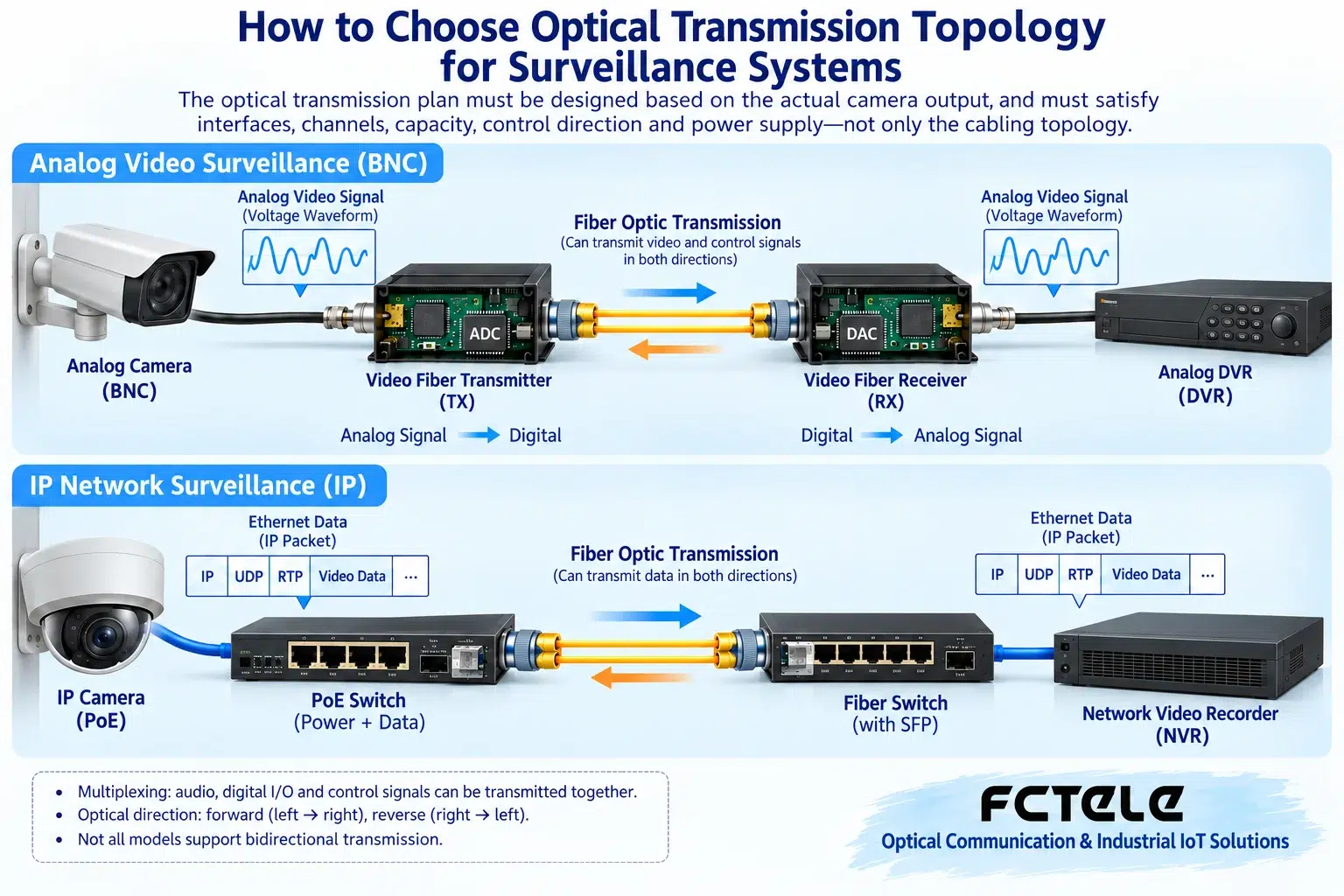
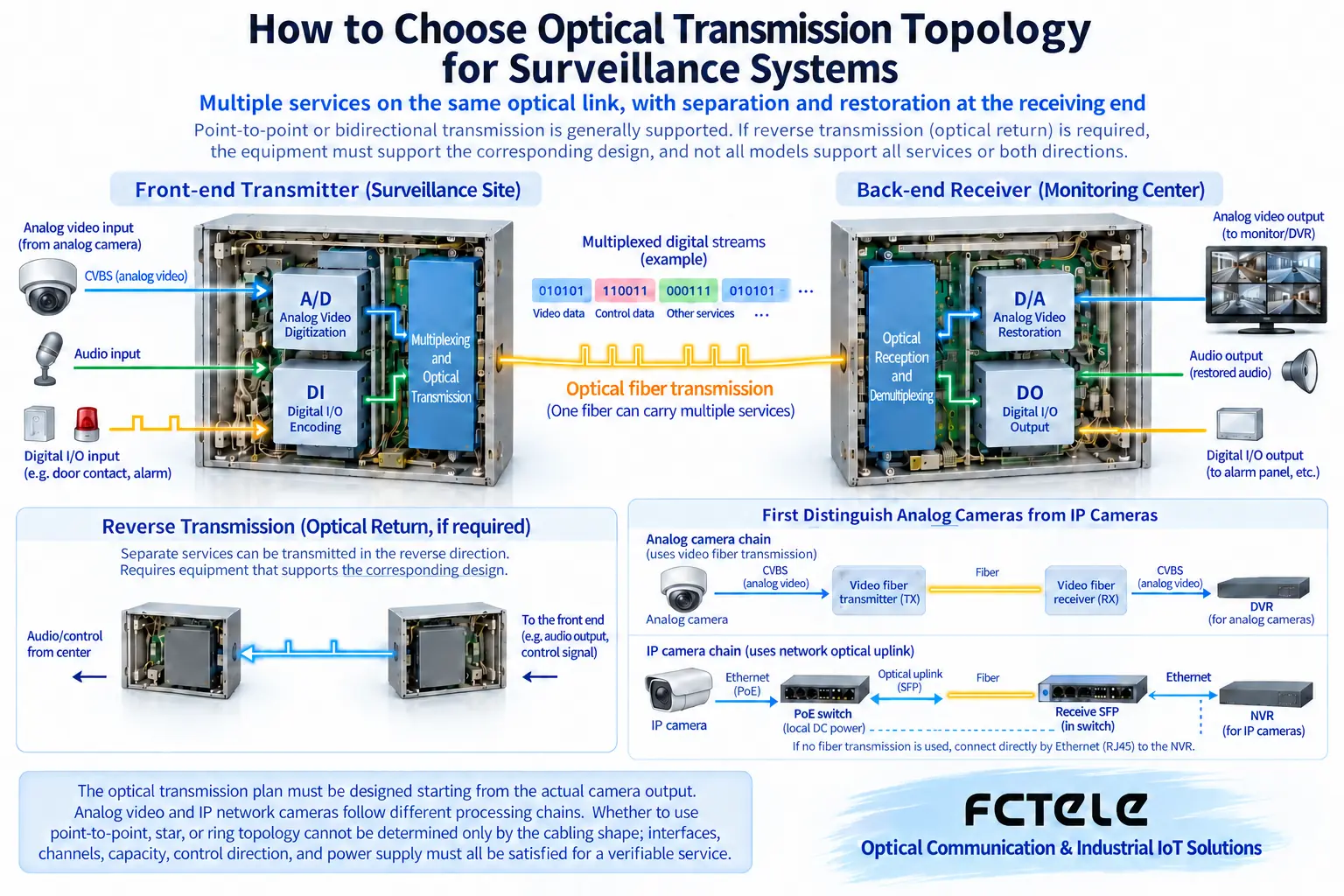
The optical transmission plan for a surveillance system must be designed starting from the actual output of the cameras. Analog video goes through a corresponding video fiber optic transmission device, while IP cameras go through a switch optical uplink; these belong to different processing chains. Point-to-point, star, or ring networks cannot be judged only by the shape of the cabling; interfaces, channels, capacity, control direction, and power supply must all be satisfied together for there to be a verifiable service.
First distinguish analog cameras from IP cameras
An analog camera outputs a specified video waveform, and the recording or display device needs a corresponding input; an IP camera sends data over a suitable network, and the receiving end needs to understand its network and application method. Digital video such as SDI has its own interfaces and formats. They can serve surveillance together, but device interoperability cannot be assumed from the same scenario. The procurement list should include camera model, output format, direction, and receiving device, to avoid writing all video as one word. Similar camera appearance does not mean the same transmission scheme is used.
How point-to-point analog optical transmission works
In a suitable digital video fiber optic transmission device, the analog input is first sampled and processed by the corresponding circuit, then enters the optical transmitter; the far end detects and restores the corresponding video output. What travels through the fiber is a signal organized by the device, not an entire picture floating in space. Both ends need matching formats and channels, and what output corresponds to one coaxial input is determined by the model design. Point-to-point makes it easy to establish a baseline, but power and line protection must also be arranged; the fact that devices at both ends can light up does not prove that the entire interface chain between camera and recorder is compatible.
What step is missing in an IP camera’s optical uplink
In an IP network solution, the switch processes Ethernet data frames, and the optical uplink extends the corresponding network link; it does not automatically sample analog video in this segment. The camera itself generates network traffic, and the recording end still needs to satisfy conditions such as address, protocol, and permissions. PoE can power the camera over a suitable copper segment, but an optical uplink does not send the same power to another building. The remote switch and other devices should have separate compliant power. Marking data, video processing, and power arrows separately can significantly reduce on-site construction ambiguity.
Why star topology requires calculating central capacity
Multiple remote ends connect separately to the center, making it easier to distinguish lines and fault scope, but central ports, receiving devices, and aggregation capacity all need planning. Multiple video streams working at the same time increase the load, and the central egress does not grow without limit just because there are many ingress points. For multi-service analog systems, also check whether the central chassis and card configuration match; for IP networks, check the uplink and recording load. Star topology does not guarantee an automatic backup path; a shared center or power supply can still become a fault point, and this must be designed separately according to availability requirements.
A ring network is not just connecting the first and last fibers
If a physical ring in an IP switching network lacks a suitable management mechanism, duplicate forwarding and traffic anomalies may occur. Devices that support the corresponding protocol are needed to manage the backup path according to rules and adjust forwarding after a fault. Analog video point-to-point devices, however, cannot be directly strung into an arbitrary ring without explicit support. Topology capability comes from devices and protocols, not from fibers forming a circle. Recovery behavior must also be proven by real service testing; it cannot be written that any ring network has zero interruption or automatically supports all brands, and control and data paths should also be understood separately.
How to add PTZ control and audio
Video usually goes from the camera to the control room, while PTZ commands may go in the reverse direction over RS485; status responses, audio, or contacts have their own directions. A multi-service fiber optic transmission device can multiplex suitable channels as designed, but the corresponding combination must actually be ordered, and serial ports, audio levels, and channel counts must be checked. You cannot assume control is normal just because video is normal, and you cannot let an unknown application protocol convert automatically. Two-wire half-duplex also requires managing the question-and-answer timing. The list should separately list source and destination ends for each service, rather than using one arrow to collectively call it surveillance transmission.
Feichang product features should land on the corresponding solution
The Feichang FCV-V4T/R official website lists four forward analog video directions and multi-service modular options, status indication; it is suitable for arranging channels around clear analog interfaces. The Feichang two-fiber four-copper managed industrial switch provides corresponding IP access, optical uplink, and RSTP function directions; the two are not substitute products for each other. Options such as PoE, audio, and control should be confirmed for the delivered version. The verifiable features cited here help with selection; they do not expand all functions into default standard equipment, nor do they claim that any unverified project has been completed.
How a hybrid upgrade can avoid replacing all equipment
Suppose an old system keeps CVBS cameras while adding IP cameras; matching analog optical transmission and network paths can be established separately, then merged by a recording or platform system with the corresponding capability. Whether they can be handled on the same platform requires checking platform support, not relying on the fiber optic transmission device to automatically change the format. First establish a single-device baseline for each, confirm video and control, then expand gradually. The example is only a method, not an implemented case. Whether old coaxial cable, chassis, and power supplies continue to be used should also be evaluated based on their condition and requirements, not skipped to save cost.
Fault verification should cover services, not just look at lights
For analog solutions, observe input and output images, control, and sound; for IP solutions, observe link errors, bitstream, recording continuity, and permissions. Both need to verify power-off restart and applicable line fault recovery. Compare normal and backup paths with the same service load, and save time and status, to avoid delivery based only on a short display. Optical power and end-face inspection help judge physical conditions but cannot replace end-to-end application verification; address errors or recording setting errors also cannot be solved by increasing optical power.
Leave a maintainable topology and channel table
The delivery drawing should mark complete device models, interfaces, transmit and receive directions, fiber cores and pairing, power, and each service, with parameters and configuration backups attached. Note which are independent point-to-point, which are network aggregation or ring networks, and which faults affect which cameras. When expanding, recalculate ports, capacity, and power, not just find an empty optical port. There is no single surveillance optical transmission topology suitable for all cameras; the correct approach is to first understand the signals, then choose devices, and finally turn the cabling plan into a reliable system through complete service verification.
Draw from the camera output forward, not backward from the fiber
First write whether the camera’s actual output is analog video or Ethernet, then write what interface the recording device receives. Analog cameras can have their service carried through a corresponding video fiber optic transmission device; IP cameras already output network data and need a matching network link. Both may involve fiber, but the intermediate processing is not the same. If PTZ control, audio, or alarms are also needed, mark their directions and interfaces separately. This service diagram determines what equipment to choose, rather than assuming any fiber optic transmission device can connect just because there is a fiber cable on site.
How multiple points converge to the center
Multiple IP cameras often converge through switches, and the central egress must carry the actual simultaneous bitstream. Analog video channels must be arranged according to the fiber optic transmission device’s actual capacity, direction, and corresponding receiving output; analog BNC signals cannot be directly plugged into a network switch. The Feichang four-channel integrated multiplexing video platform can carry multiple services according to configuration, but each additional function must be checked against the delivery list. Node count, power location, cable paths, and maintenance requirements should all be written into the topology, to avoid discovering only after the central equipment arrives that remote service interfaces do not match.
A fault test should observe all services
Only the image recovering does not mean PTZ, audio, and alarms have also recovered. Where maintenance permits, separately verify link disconnection, reconnection, and device power cycling, and observe recording continuity, control response, and alarm records. Do not casually unplug fibers for testing in an important running system; arrange a window and fallback plan first. Finally, map the result of each service to the original topology diagram, and record configuration, version, and actual impact. This way, when expanding later, you know which link still has margin and which faults affect which points.
Product and principle verification materials:Feichang product details 218;Feichang product details 3243. The general mechanisms and hypothetical examples in the main text do not replace the corresponding model manuals.
Translated from the Chinese technical article. Source first published: 2020-05-06. Source last revised: 2026-10-13T22:21:36+08:00. Read the Chinese source
