


Maintaining an industrial switch is not about restarting it once a day, and it is not enough to just wipe the enclosure clean. Effective maintenance keeps power supply, heat dissipation, interfaces, and configuration continuously within allowed ranges, and leaves comparable records. First understand the normal state, so that when changes appear, hidden problems can be found in time.
1. First establish a normal-state record
Label the switch, ports, and cables with matching numbers, and save the actual wiring topology, device model, firmware version, and configuration backup. Record which ports connect to PLCs, cameras, host computers, and other switches, and which belong to a ring network and which are ordinary access ports. Without an accurate topology, maintenance personnel may unplug the wrong production link, or treat a standby line as an idle cable.
When the device is running normally, save the power supply status, temperature, port speed, link up/down counts, and error counters as a baseline. A baseline is not a one-time screenshot, but a repeatable state under the same type of business load. For example, camera traffic may differ between day and night, so it should be recorded separately; when comparing later, choose similar conditions to avoid mistaking normal changes for faults.
Set the inspection cycle according to business risk, environment, and the manufacturer’s manual. Critical control devices, dusty cabinets, or outdoor devices should be observed more closely than non-critical nodes in a clean indoor room. Do not directly apply a uniform rule such as “open and clean dust every day” or “upgrade every month”; the maintenance action itself may also cause an interruption.
2. Environmental maintenance: give heat a path to leave
Switch chips, power supplies, and PoE power supply sections generate heat. Fanless devices usually rely on internal heat conduction structures, the metal enclosure, and surrounding air to dissipate heat. Placing other heat-generating devices tightly against the enclosure, covering heat dissipation slots with cable bundles, or accumulating dust inside the cabinet will all change the conditions for heat to leave. A metal enclosure can only help conduct heat; it cannot guarantee the device will never overheat.
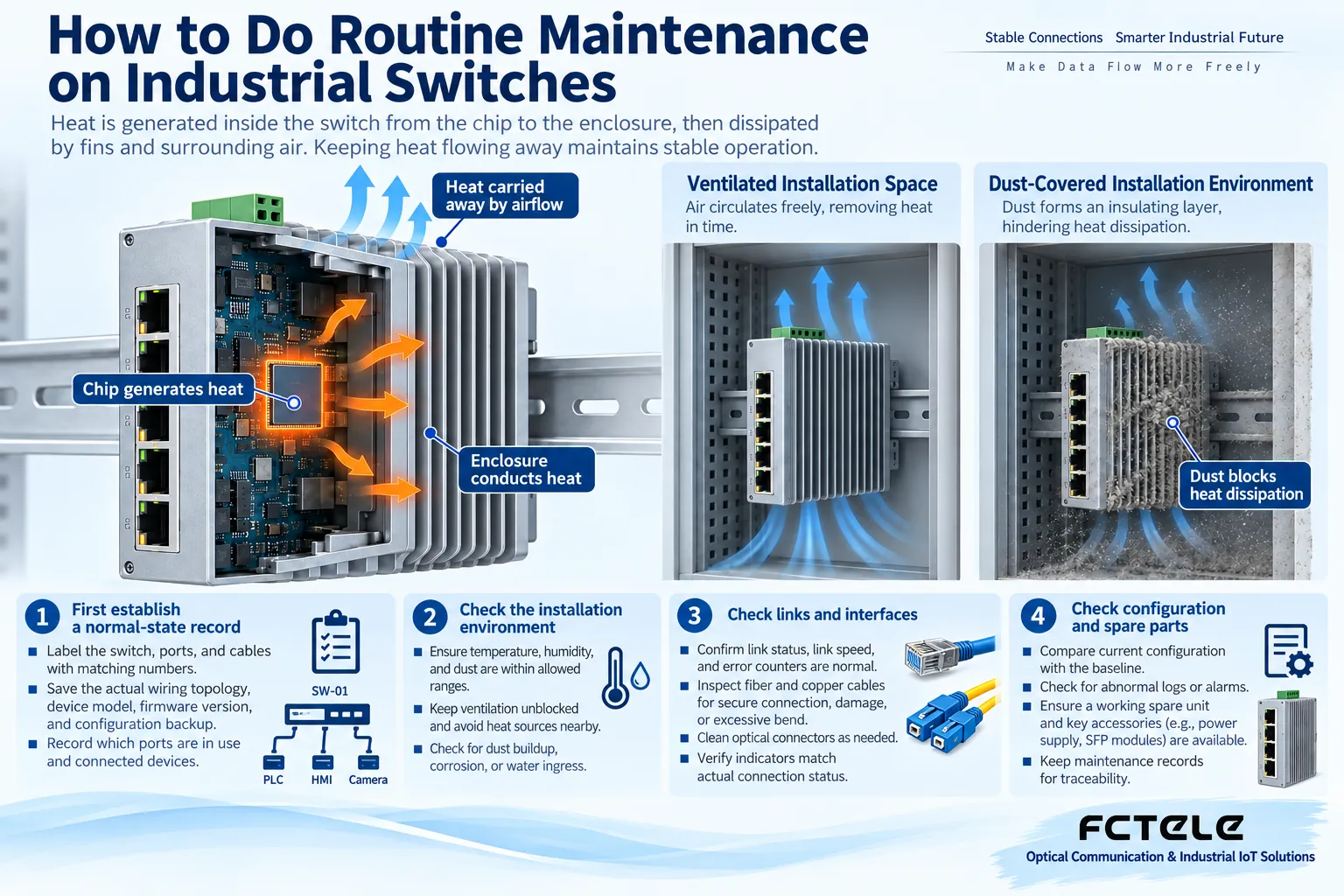
Keep spacing according to the installation manual, and check cabinet temperature, condensation, water accumulation, and corrosion. Record the device operating temperature range, but do not mix enclosure temperature, chip temperature, and ambient temperature into one number. Humidity conditions usually also include a “no condensation” requirement. Outdoor day-night temperature differences may cause condensation inside the cabinet, so check even if it looks very dry during the day.
Before cleaning, confirm whether power needs to be cut off and whether on-site operation is allowed, and use methods approved by the manufacturer. Do not spray cleaning liquid onto a powered device, do not blow compressed air directly into optical ports, and do not scrape terminals with hard tools. Live measurement and power supply repair should be performed by qualified personnel; if there is a burning smell, charring, or water ingress, shut down according to safety procedures instead of treating it as ordinary upkeep.
3. Power supply and cables: check for changes, do not plug and unplug at will
Check whether power terminals are loose, whether cables are under tension, whether grounding is reliable, and whether there are abnormal records in the upstream power supply. Dual-power-supply units should record the status of each power feed and confirm the source of both feeds and their common failure points. To verify whether the device still works when one feed is lost, arrange a maintenance window and monitor the business result, rather than casually unplugging power during production.
Inspect network cable jackets, connector latches, bends, and cabling paths; optical fibers should have an appropriate bend radius, clear fiber core labels, and end-face protection. Dirty connectors may reduce received optical power, but frequent plugging and unplugging will introduce more contamination. Only when inspection is needed, follow dedicated end-face inspection and cleaning procedures; do not look directly into optical ports.
Managed devices can observe optical module diagnostics, error frames, discarded frames, and link changes. Pay attention to increments over a period of time, and judge together with repairs, device startups, and environmental changes. An indicator light being constantly on is not necessarily a fault; some lights being constantly on means the link has been established; the actual meaning must be checked in the manual for the corresponding model. A normal light and normal business are also not the same conclusion.
4. What exactly needs maintenance in “autonegotiation”?
The autonegotiation mentioned in older articles mainly refers to Ethernet autonegotiation: when a link is established, the two adjacent ends exchange their supported capabilities and choose a commonly supported operating mode. It happens at the physical layer, is not completed by the host computer sending ordinary IP packets, and does not mean the device will automatically repair a bad network cable.
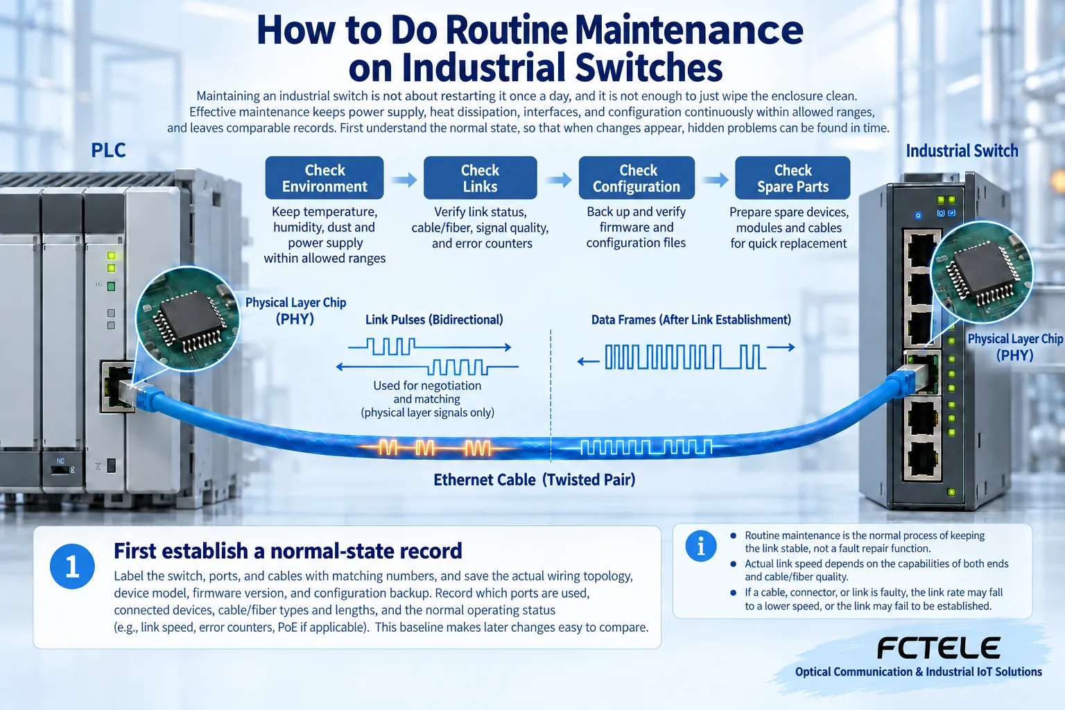
Daily inspection should compare the actual negotiated speed with the design value. If a port that should be gigabit becomes 100 Mbps, first check the terminal capability, the four-pair connection of the network cable, and the port configuration, then determine whether it is abnormal. Higher speed and more business are not necessarily the same problem. Fixed parameters should only be used when the manufacturer explicitly requires it, and the opposite end should be checked at the same time. You cannot consider it done just by forcing full duplex on the switch side.
5. Configuration and software: being able to recover is more important than frequent changes
Regularly verify whether the configuration backup can be read, and record the backup date and applicable firmware version. The running configuration and the startup configuration may differ. After changes, save according to the platform requirements, and verify which one will be used after restart. Backup files may contain accounts, addresses, and keys, so they should be placed in a location with access control and not casually shared with unrelated personnel.
Check management account permissions, idle accounts, and remote access scope. Maintenance terminals should maintain security updates, but do not apply the old articles’ mentions of floppy disks, tapes, or audio source checks: these are not common maintenance objects for industrial Ethernet switches. Evaluate software issues through logs and manufacturer announcements. Before upgrading, verify hardware and firmware matching, configuration compatibility, and rollback methods.
When configuring VLANs, ring networks, and QoS, first explain the purpose and scope of impact of the change, save the differences before and after the change, and then test the business. Fewer alarms do not prove the network is better; it may be that monitoring functions have been turned off. Do not disable necessary protection protocols just to make alarms disappear, and do not use a default shared account to maintain all devices for a long time.
6. Preventive maintenance and acceptance
Prepare confirmed power supplies, optical modules, short network cables, and similar spare devices, and record the model, version, and replaceable range. It is not enough for a spare device to power on; its ports, configuration, and business capabilities need to be verified. The wavelength, speed, and single-mode/multimode type of stocked optical modules must match; they cannot be considered interchangeable just because the interface is the same.
After maintenance is completed, check the real business, not just ping the management address. Observe terminal response, error counters, link stability, and ring network status, and confirm that labels, configuration backups, and actual wiring are consistent. Keep records of discovered problems, handling process, and retest results. To further locate faults, you can read article 1675 on industrial switch troubleshooting on this site.
Feichang Technology DIN-rail industrial switches include different power supply and network management configurations. For specific selection, check the corresponding product details and manual. During maintenance, convert the model’s supported capabilities into checkable items, rather than generalizing wide temperature, redundancy, or management functions to all devices.
References:Cisco autonegotiation explanation,Feichang Technology DIN-rail industrial switches. This absorbs the environmental maintenance, backup system, and autonegotiation content of 1731, 1094, 2162, and 2254; the figures are generic mechanism illustrations, not actual product photos.
Translated from the Chinese technical article. Source first published: 2021-03-10. Source last revised: 2026-10-13T19:28:50+08:00. Read the Chinese source
