


Industrial switches solve the problem of forwarding data between devices. How they find the exit, why they queue, and what management and redundancy can do are key to understanding common faults. Do not think of industrial devices as universal gateways that automatically recognize all production commands, and do not treat a lit port as proof that the entire business link is normal. First understand how data travels, then check model capabilities, so you can ask useful questions.
What does a switch do first after receiving data?
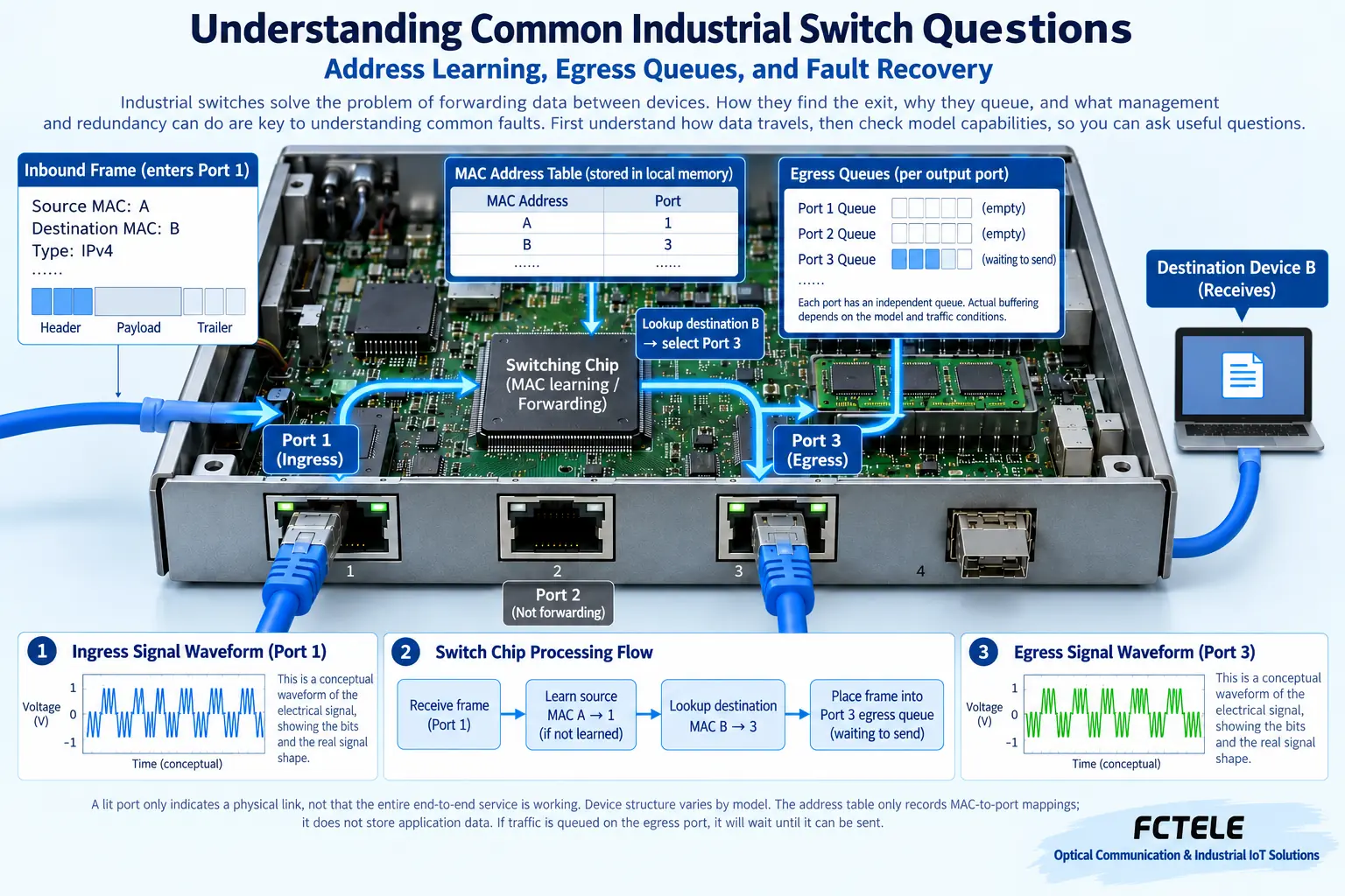
Ethernet organizes data into frames, and each frame carries a link-layer source MAC address and destination MAC address. MAC can be understood as the address used at this layer, and it is not the same kind of information as the IP set in an application. After a switch receives a frame, it checks and processes it according to the relevant rules, learns from the source MAC which port the device is on, then looks up the destination address to decide the exit.
Therefore, the address table is not a map with all computer locations written in advance, but can be updated as data is received. After a device moves to another port, the newly received source address can help update its location. Dynamic entries also age out, and the specific time depends on the implementation and settings; do not treat one example time as a fixed value for all devices. Static entries and dynamic learning have different maintenance methods.
Why does it send to multiple places when the destination address is not found?
If the switch has not yet learned the destination location, it usually forwards within its broadcast domain to other allowed ports, rather than guessing a single exit. Broadcasts and some multicasts also have their own handling rules. Other ports here do not mean unlimited transmission across all networks; VLANs, port status, and corresponding filtering rules affect the scope.
When the destination device responds, the source address of its frame is learned, and subsequent known unicast can point to the corresponding port. This process explains why forwarding behavior may differ between a newly connected device and one after stable operation. When unknown unicast and broadcast volumes are abnormal, check the topology, address changes, and traffic sources; do not immediately assert that the switching chip is broken, and do not simply shut down all broadcasts to try your luck.
The address table and the buffer queue are not the same thing
The address table answers where to send, while the egress queue temporarily stores frames waiting to be sent. You can compare it to the destination records during parcel sorting and the goods waiting to depart, but a real network also considers frame order, priority, and port rate. The two solve different problems: increasing address table capacity cannot directly solve egress congestion, and increasing buffer cannot permanently make up for insufficient bandwidth.
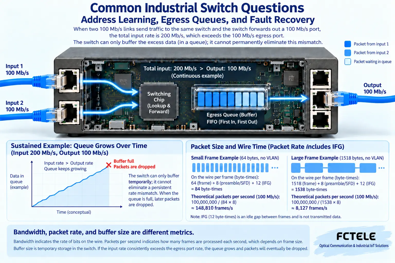
If data from several ingress ports all needs to pass through the same egress, the egress can only send at its allowed rate. Short bursts can be temporarily stored, but when continuous input exceeds output, the queue will grow and may eventually drop packets. When uplink traffic is very high, calculate the aggregated services and peaks, rather than only asking about the number of terminals. Many idle devices may not cause congestion, while a few high-traffic devices may fill the egress.
Why should Gbps and packets per second be viewed separately?
The nominal port rate describes the transmission capability of a certain interface, switching capacity is usually used to describe the device’s overall internal forwarding scale, and packets per second reflects the ability to process the number of frames. For frames of different sizes, even if the total data volume is close, the number of frames that need to be processed may differ. Therefore, a very large internal capacity number cannot prove that any service combination will definitely not encounter a bottleneck.
When reading parameters, confirm the test conditions, frame size, and statistical basis, especially distinguishing bidirectional totals from unidirectional actual services. Application payload is also affected by protocol overhead and link conditions. On site, under authorized conditions, measure actual traffic, error counters, packet loss, and latency changes, and check whether the uplink and terminals are bottlenecks, rather than relying only on the largest number on a promotional page.
Priority can improve waiting, but it cannot create bandwidth
Quality of service mechanisms are often abbreviated as QoS. Within the range supported by the device, they can classify and schedule different services. For example, when the egress is temporarily congested, a certain type of important data is processed first. But queue rules, identification methods, and scheduling capabilities depend on the specific device implementation; you cannot guarantee that an application will meet real-time requirements just by enabling a certain name.
Priority also cannot make a continuously insufficient egress magically gain capacity. If total demand exceeds available bandwidth for a long time, you still need to reduce services, adjust the topology, or upgrade the link. Too much high-priority traffic will also affect other services. Production control networks should be planned and verified based on actual requirements; do not treat QoS, industrial labeling, or wide-temperature design as proof of automatically achieving deterministic communication.
Why are management functions helpful for troubleshooting?
Managed devices may let maintenance personnel view port rate, link changes, traffic, or error statistics, and may also support VLAN and spanning tree. Specific functions are subject to the model, firmware, and version. Unmanaged devices are not incapable of forwarding, but usually lack the same configuration and observation capabilities; selection should consider maintenance needs, not simply compare the length of feature lists.
The Feichang Technology managed industrial switch details list corresponding STP, RSTP, and other capabilities, which can provide a selection basis for networks that need controlled redundancy. But Layer 2 management is not equivalent to Layer 3 routing, and it certainly does not mean the device already has all firewall, protocol gateway, or industrial security functions. Management access also requires permissions, configuration backup, and security maintenance, and should not be exposed arbitrarily for convenience.
Why can’t ordinary ports be directly connected into a loop?
Ethernet frames may be repeatedly forwarded in an uncontrolled loop, and broadcasts and unknown-destination data will be amplified, causing network congestion. Redundant physical links are originally intended to provide another path after one point breaks, but appropriate protocols must manage service forwarding. Physically connecting into a ring and logically allowing which paths to send data are two different things.
Spanning tree will restrict certain service forwarding paths according to protocol rules and reconverge after a fault. Recovery time and service loss depend on the device, protocol, topology, and application, and zero packet loss cannot be universally promised. Not every site must use a ring network; simple point-to-point or star structures may also meet requirements. Whether redundancy is needed should start from risk and service tolerance, not from looking advanced.
How to troubleshoot an example of uplink congestion?
Suppose multiple collection terminals send data to a server at the same time. Normally it is fine, but delays appear when centralized reporting occurs. First record the egress traffic, queue-related behavior, and error counters at the time of occurrence. If each electrical port negotiates stably and only the aggregation egress approaches its capability limit during the centralized period, prioritize checking service aggregation and bursts, rather than replacing all patch cords.
Then, under allowed conditions, stagger reporting, adjust data volume, or use an uplink that meets requirements, and compare whether the phenomenon improves. Change only one variable at a time and record continuous operation results. If traffic is not high but the link repeatedly disconnects, return to power supply, environment, and physical connection layers to continue troubleshooting. Different evidence leads to different checks; do not uniformly explain slow networks as one cause.
Acceptance must answer whether actual services meet requirements
After installation or adjustment, confirm bidirectional services, continuous load, port negotiation, and alarm status. When redundancy is needed, perform specified fault tests during an authorized maintenance window and confirm that real applications are normal after recovery. Ping, lit indicators, and a single file transfer each provide partial evidence, but none alone can prove that all service conditions have been met.
Keep device model, firmware, topology, configuration, and test results so that subsequent maintenance has a reliable baseline. By understanding the four mechanisms of address learning, egress queuing, management observation, and controlled recovery, you can turn a vague ‘is the device good?’ into questions that can be checked: do the interfaces match, is capacity sufficient, can the phenomenon be observed, and does the fault recover within the allowed range.
Verification materials:Ethernet switching mechanisms;Feichang Technology managed industrial switches. The diagram explains general mechanisms and is not a wiring diagram for a specific model.
Translated from the Chinese technical article. Source first published: 2021-04-02. Source last revised: 2026-10-13T20:37:04+08:00. Read the Chinese source
