


After powering on a telephone fiber optic transmission device, you cannot judge that the whole system is normal by “how many lights are on.” First confirm whether it only has analog telephones or also carries E1 and other services. Telephones require testing calls, ringing, and two-way voice. E1 requires checking the digital interface, framing, and clock, then performing loopback and bit error tests within the specified range. The two types of services sharing one optical path does not mean one test can replace the other.
First separate telephone ports from E1 ports
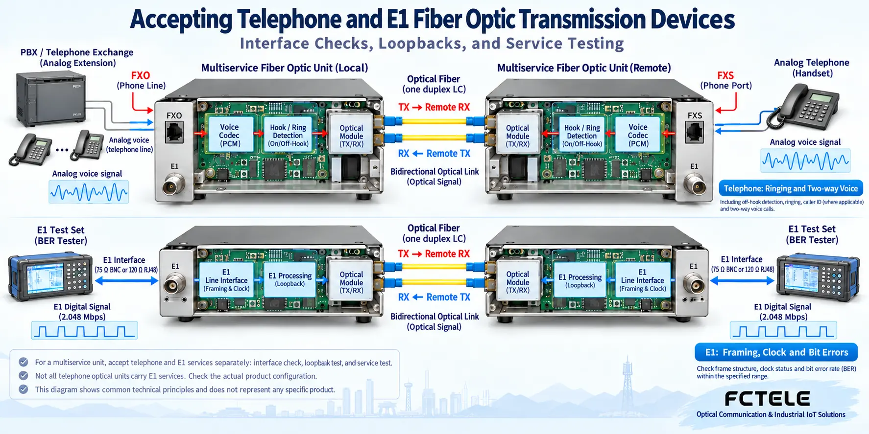
Analog telephone ports handle voice and line states such as off-hook, on-hook, and ringing. FXS is the side that provides line feed and ringing conditions. FXO is the side that uses this line and presents off-hook/on-hook states. A typical extension is: the switch’s analog extension port connects to the near-end FXO, and the far-end FXS connects to an ordinary analog telephone. Digital proprietary extensions, IP telephones, and analog telephones are not the same type of interface. Similar connectors cannot be directly interconnected.
E1 is a digital transmission interface with a line rate of 2.048 Mbit/s. It can carry specified time slots and services, but an E1 socket is not an ordinary telephone socket. How telephones are mapped into time slots and what signaling is used depends on the equipment and the far-end system. A pure telephone fiber optic transmission device does not necessarily provide E1 externally. A multi-service fiber optic transmission device with E1 cannot be assumed to support the digital trunk of any telephone switch.
First draw the topology: “end device—local interface—fiber optic transmission device—optical fiber—far-end fiber optic transmission device—far-end interface.” Fill in the number of telephone channels, FXS/FXO roles, whether E1 is present, port numbers, and power supply item by item. Listing voice services and E1 services separately in the acceptance table is more reliable than copying light colors and port names from old documents.
How to perform power-on and short-link back-to-back testing
Before power-on, check the power supply voltage, polarity, capacity, and grounding requirements. Do not assume the power supply is suitable just because the connector can be inserted. Record the models, versions, and pairing method at both ends, then use a known-good short cable to establish a minimal test. The optical receive power should be within the equipment’s allowed range. When short-connecting long-distance equipment, also pay attention to the overload upper limit. Necessary attenuation measures should be carried out according to the manufacturer’s instructions.
Dual-fiber equipment usually connects the local TX to the far-end RX, and uses another fiber core for the reverse direction. Bidirectional single-fiber equipment requires checking the paired wavelengths and transmission system. You cannot arbitrarily perform optical port self-loopback on each unit. LOS is often used to indicate loss of signal, but the specific light name, color, flashing, and normal state must be checked in that model’s manual. After self-loopback, if a certain light goes out, it only means the conditions within that test range have changed. It does not prove that the far-end telephone can make normal calls.
First save the back-to-back configuration and alarm baseline, then connect the on-site optical cable. If the short link is normal but the on-site link is abnormal, compare the receive power at both ends, splice loss, power supply, and environment. If the short link is also abnormal, first deal with equipment pairing and interface configuration. Change only one condition at a time, and record whether the fault moves with the telephone, cable, or port.
For analog telephones, test the complete call first, then check noise
Use a normal switch analog extension port, a single normal telephone, and a short telephone cable to verify off-hook, dial tone, dialing out, incoming ringing, answering, two-way voice, and release when both parties hang up. Establish an extension number and port correspondence table for each channel, to avoid “the first channel works” masking wrong connections or crosstalk on other channels. Caller ID, fax, and special release signaling should be listed as separate items. Do not replace compatibility confirmation with hearing sound.
When noise or volume is abnormal, compare the results of a direct switch connection and a connection through the fiber optic transmission device. Check the local telephone line, connectors, load, grounding, and interference, then locate the issue using optical path alarms and bit error evidence. You cannot attribute all noise to the optical fiber just because the equipment passed factory testing. Connecting multiple telephones in parallel changes ringing and line load. Check the supported quantity and line length according to the model. Do not treat a certain kilometer figure from an old document as a universal upper limit.
Why E1 requires checking impedance, framing, and clock
Common E1 interfaces include 75Ω unbalanced coaxial form and 120Ω balanced line form. What must match is each fiber optic transmission device and its locally connected E1 equipment. The two ends of the optical fiber do not have to mechanically use the same electrical interface, but the equipment must support the corresponding transmission combination. Adapter connectors do not automatically complete correct impedance matching. The specific pins of RJ-type connectors also need to be wired according to the manual.
Also confirm framed or unframed mode, line coding, valid time slots, signaling method, and clock source. The clock determines the rhythm by which digital bits are recovered. Improper role configuration on both sides may cause slips or intermittent errors. When the optical port is normal but E1 alarms occur, check the local E1 transmit and receive connections and configuration, then determine whether the far end is providing a valid signal. Do not only stare at the common optical path.
What loopback results can prove
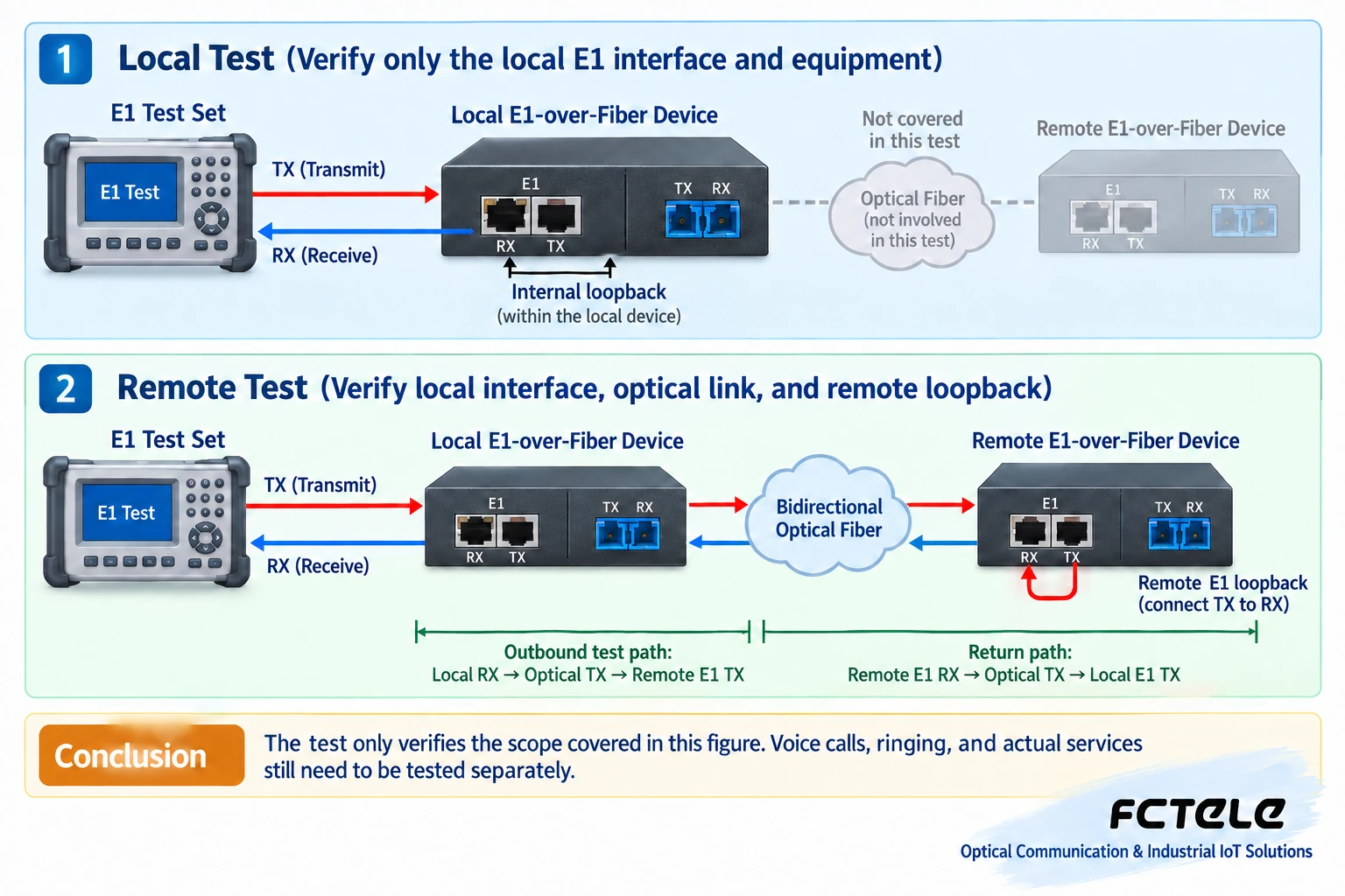
Loopback sends the transmitted test signal back to the receiver at a specified location, to narrow down the fault range. A local E1 loopback may only verify the tester, cable, and local interface. A far-end loopback through the optical path also involves transmission at both ends and the optical fiber. Local, far-end, line, or payload loopback in the equipment menu are not the same range. First check the actual return point, then interpret the test results.
During a maintenance window, enable supported loopbacks according to the manual. Use a tester, cable, and test pattern suitable for the interface. Record transmit, receive, synchronization, bit errors, slips, and alarms. Testing will interrupt or change services. After finishing, cancel the loopback and restore the configuration, then run real telephone and E1 services. Do not write “LOS off after self-loopback” as absolute equipment normality, and do not use one loopback result to assert that all ports are intact.
Use symptoms to decide which section to check first
If the equipment cannot power on, check the power supply and wiring first, not the optical fiber or service configuration. If all telephones and E1 are interrupted at the same time, check the common power supply, equipment operation, and optical path first. If only one telephone channel is abnormal, check the channel, telephone, and local line first. If telephones are normal but E1 does not work, focus on checking the E1 interface and digital configuration. This is more directed than restarting all services together.
For example, if one E1 passes testing in local loopback, but after canceling the loopback it still has errors through the on-site optical fiber to the far end, this only means the problem was not found within the local return range. Next, compare the far-end E1 wiring, clocks at both ends, and the optical link. You cannot directly conclude that the far-end equipment is damaged. Also check whether the tester is truly synchronized and whether the pattern and framing settings are consistent, to avoid mistaking a test configuration error for a transmission fault.
Write the test time, topology, return point, duration, and error type in the measurement results. No errors on the line for a short time does not mean there will be no errors under all temperature, power supply, and service conditions. The acceptance period and pass threshold are determined by project agreements and equipment documentation. You cannot derive measured specifications from the waveforms in this article’s illustrations.
Arrange acceptance according to specific Feichang Technology products
Feichang Technology FCP-O16/FCP-S16 desktop telephone fiber optic transmission device The documentation describes 1–16 FXO/FXS telephone channels and corresponding management capabilities. It is suitable to start checking from analog interface and channel requirements. When E1 transmission is needed, check separately E1 optical modem or the corresponding integrated service series. The documentation for a pure telephone model cannot prove that it provides E1 externally. Manufacturer confirmation should be tied to the specific ordered model, version, and interface combination.
For final delivery, retain the topology, port table, configuration, optical power at both ends, per-channel call records, and E1 test records. Then verify alarms for fiber break and power loss, and the actual services after recovery. Telephone lines may have ringing voltage. Use suitable instruments for measurement and have capable personnel perform the operation. Do not look directly into optical ports. The goal of complete acceptance is to be able to reproduce each service and fault boundary, not to take a photo of a lit indicator.
References:ITU-T G.703 digital interface specifications and the above Feichang Technology product documentation. This article corrects the old document’s generalizations of light colors, self-loopback methods, and single-fiber pairing parameters. The schematic diagrams are generic mechanism illustrations, not specific product internal structures or measured data.
Translated from the Chinese technical article. Source first published: 2022-07-06. Source last revised: 2026-10-13T20:24:48+08:00. Read the Chinese source
