


Explain the wiring of Ethernet fiber switches from MAC forwarding and optical port transmission and reception, and describe speed, VLAN, uplink bandwidth, and service acceptance.
First confirm that this is about Ethernet switches
“Fiber switch” is often used to describe an Ethernet switch with optical ports, and it may also refer to a Fibre Channel switch in a storage network. This article only discusses the former: cameras, control terminals, and servers use the Ethernet protocol, and the switch sends and receives Ethernet frames through electrical ports or optical ports. An FC storage switch is not something that can join this kind of network just by changing a fiber cable; the service protocols and access devices of the two are different, so you should first confirm the product object from the device nameplate and manual.
A typical scenario is multiple remote terminals connecting to one switch, and then using fiber to uplink to the center. Fiber solves the transmission medium and distance conditions, while the switch solves forwarding between multiple ports. It does not automatically assign all IP addresses, and it does not expand uplink bandwidth without limit. Before installation, you should list the number of terminals, port speeds, service direction, uplink path, and power conditions, and then decide the port combination.
How a frame of data shows what happens internally
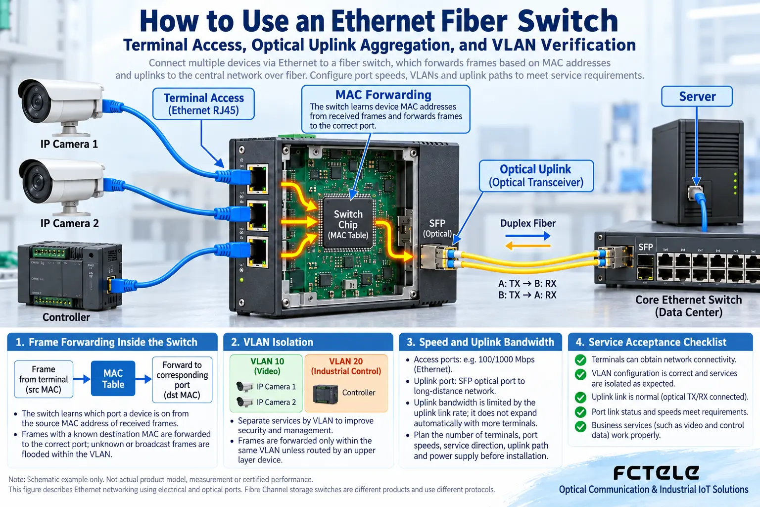
Data sent by a terminal enters a port in the form of frames. A MAC address is the link-layer identifier of an Ethernet interface, and the switch learns which port a device is on by the source address of received frames. After that, when a frame with a known destination address is received, it usually chooses the corresponding exit to forward it; the handling of broadcast and unknown destination addresses is also limited by scope such as VLAN. When the device restarts, addresses age out, or a terminal moves to another port, the learning result also changes.
On the optical port side, the module converts the optical signal into an internal electrical signal, the switching chip reads the frame and decides the egress port, and the target port then generates the corresponding electrical or optical signal. Therefore, an optical port is not a direct-through channel that bypasses switching processing. The chip buffer can temporarily store frames waiting to be sent, but the buffer has an upper limit, and when multiple inputs send to one output at the same time, queuing and dropping can still occur. Comparing a switch to a road intersection helps with understanding direction selection, but actual forwarding depends on addresses, table entries, and configuration.
Check optical conditions item by item before wiring
Electrical port connections require checking cable category, length, shielding, and the speeds supported by the port; optical ports require checking module package, host support, service speed, fiber type, and optical budget. Dual-fiber usually requires transmit and receive to be crossed correspondingly, and single-fiber bidirectional requires matching wavelengths. The nominal transmission distance is only one selection condition; on-site connectors and splice loss will change the margin. Connector shape compatibility also cannot replace protocol compatibility.
For actual installation, you can first use a short link to confirm the device combination, and then use the on-site fiber cable. Record each port number to avoid mistakenly plugging a service line into a dedicated management port. Insert and remove modules and connect power according to the instructions, and handle fiber bend radius, fixing, and connector cleaning according to the cable requirements. Do not look directly into an optical port. Check power supply capability and data connection separately; the fact that a switch has electrical ports does not mean those ports have PoE output.
VLAN configuration must correspond at both ends
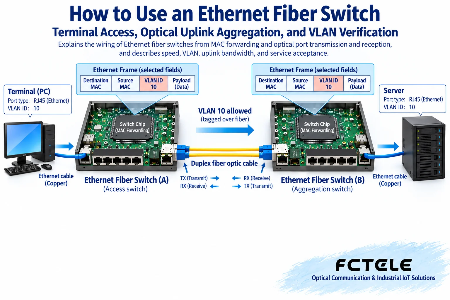
VLAN is a method of dividing an Ethernet Layer 2 network into different logical broadcast scopes. An access port connected to an ordinary terminal usually assigns received untagged frames to a specified VLAN; an uplink port connected to another switch may pass tagged frames, or may use untagged services according to configuration. A tag contains a VLAN identifier, but whether the terminal will process the tag must be confirmed separately. You cannot assume that the entire uplink automatically matches just because you set the VLAN number at one end.
For example, if cameras are assigned to VLAN 10, the central recording server must also be on a path that can reach VLAN 10. The uplink between the two switches needs to allow this VLAN to pass, and handle the corresponding tagged and untagged frames consistently. If the server is on another subnet, routing and access policies are also needed. When troubleshooting, first clarify what mode each port is in, then check VLAN membership and default VLAN assignment; do not skip Layer 2 configuration just because IP addresses look similar.
Use service load to evaluate whether the uplink is sufficient
There is no unified answer such as “one hundred twenty units” or “three hundred units” for how many terminals a switch can connect. Actual limits include available ports, effective uplink bandwidth, traffic per terminal, service concurrency, forwarding table and configuration capacity. Two low-traffic controllers and two high-bitrate cameras place different demands on the same uplink. Adding up the nominal speeds of multiple electrical ports also cannot prove that one slower fiber uplink is definitely sufficient.
For acceptance, you can first verify a single service channel, then run the terminals planned for use at the same time, and observe latency, packet loss, recording continuity, and port drop counters. Replacing a loaded test with one successful ping during idle time can easily miss queuing problems. The VLAN, port mirroring, statistics, and spanning tree functions in Feichang Technology managed switch materials can serve as a reference when choosing specific models that support these verification methods; they must be confirmed model by model, and network management functions cannot be applied to all unmanaged switches.
Record the management path and the service path together
The fact that a management computer can log in to the switch does not mean all terminals can reach the server. The management address may be on a separate VLAN or dedicated interface, while services use another group of ports. In on-site records, the management access method and service path should be written separately to avoid isolating yourself outside the management interface after changing a port mode. Before remote changes, prepare a configuration backup and on-site recovery method, and arrange a verification window; operations requiring on-site wiring should be performed by personnel familiar with the device instructions.
How to Arrange Safety, Troubleshooting, and Maintenance
When an optical port does not light up, first check power, module support, speed, and fiber transmit-receive correspondence; when the optical port is lit but services do not work, then check VLAN, IP, routing, and the application. For intermittent interruptions, correlate port logs, error counters, link changes, and service times. If a storm occurs or services in multiple places become unstable at the same time, check whether a Layer 2 loop was mistakenly connected; before adding a backup line, confirm that both ends support and correctly configure loop prevention mechanisms.
During maintenance, keep the port table, VLAN table, module specifications, and configuration backup. After changing one configuration item, first verify the affected services, then expand the test. When replacing a switch, check the original port modes, optical module support, and management address at the same time; do not buy a replacement based only on the number of ports. The basis for final delivery is that the entire path from terminal to server passes verification, not that the device name contains the word “fiber,” or that one port indicator light shows normal.
Materials and figure notes
The main text is written based on the device working mechanism and the following materials; specific specifications are subject to the ordered model and the latest manual. The figures are general mechanism diagrams.
Cisco SFP installation and safety instructions;Cisco spanning tree principle instructions;Feichang Technology B-series Ethernet fiber transceiver materials;Feichang Technology managed industrial Ethernet switch function materials
Translated from the Chinese technical article. Source first published: 2019-11-01. Source last revised: 2026-10-13T18:52:49+08:00. Read the Chinese source
