


Industrial switches have wide-temperature or immunity data, but they still need to be validated under the project’s power supply, installation, and communication load. Field load validation must answer: when the environment changes, does the service stop, where does the abnormality occur, and does recovery meet the requirement. It is not about letting users create high-voltage interference at will, nor about applying all stresses to the device at the same time. First establish a normal baseline, then change conditions one by one, and finally verify a professionally evaluated combination of conditions, so the results are easy to explain.
1. What exactly is being carried under load
Here, load includes both the device’s power supply and heat generation, and the network traffic it actually forwards. Connecting only one cable and occasionally sending a few Ping packets can check basic connectivity, but it is hard to reflect the pressure of video, control messages, or multi-port aggregation. Continuous service puts ports, the switching chip, and queues in different states, and the device’s heat must also be discharged through the casing and surrounding air.
Think of the network as a road with multiple entrances: an empty road being passable does not mean there will be no queuing when vehicles concentrate at the same exit. But this analogy cannot be used to derive precise bandwidth and recovery times. Actual testing needs to clearly state frame length, traffic direction, average rate, burst characteristics, and the ports used at the same time. In particular, check the case where multiple inputs converge to one slower output, to avoid mistaking reasonable output congestion for an environmental fault.
2. First keep a normal state, then talk about abnormalities
Under conditions suitable for the device and electrically safe, save the delivered model, hardware version, firmware, configuration, power supply, and optical module information. Record the send and receive counts of continuous service, port errors, device restarts, and application alarms to form a comparable baseline. Before testing, also confirm how to stop when an abnormality occurs, who handles it, and how to restore the original configuration. Fault drills in production systems should be conducted in an approved maintenance window or an isolated test network.
Counters are usually cumulative values. You cannot conclude that errors are still occurring just because you see a very large number. A more useful method is to record the increment over the same time period and align the timestamps of the sender, receiver, switch, and application logs. So-called packet loss means data sent within a specified observation range that is not received as expected; subtracting two cumulative totals collected at different times may lead to a wrong conclusion.
3. How ambient temperature works together with device heat
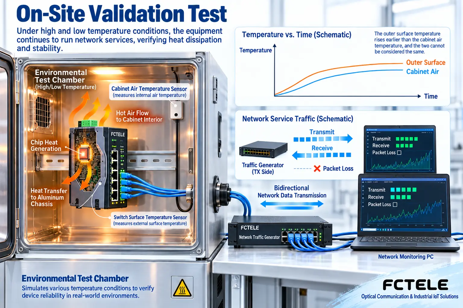
The switching chip generates heat when working. Heat first transfers to the heat dissipation structure and casing, then is released through the surrounding air and installation environment. The hotter the environment, the smaller the heat removal margin usually is; installing devices too densely or blocking the air inlet and outlet paths will also change the result. A fanless design reduces the fan as a maintenance component, but it still needs suitable installation spacing and heat dissipation conditions. It cannot be understood as producing no heat.
Professional environmental testing should be carried out according to applicable methods and model conditions. Air temperature, casing temperature, and chip temperature are different measurement objects, and their rates of change are not exactly the same. Cold start, continuous operation, dry heat, damp heat, and temperature change each answer different questions. Do not use one dry heat test to replace all environmental validation. The public description of IEC 60068-2-2:2025 distinguishes dry heat testing from the evaluation of temperature change effects. Projects should choose the correct method accordingly, rather than setting their own temperature and duration.
4. Separate and locate power supply and communication problems
If the whole device restarts when the temperature changes, check the input voltage, power supply alarms, and startup logs at the same time. If the device does not restart but some ports have errors, then check cables, modules, connections, and port counters. Change one condition at a time. For example, first keep the network configuration unchanged and check installation heat dissipation; then restore the baseline and check another item. All measurements and power operations should be carried out by personnel with the corresponding conditions. Ordinary users should not open powered devices to probe internal terminals.
Dual power supplies also need to be validated according to the delivered configuration. Having two input terminals does not mean the two paths already come from independent power sources, and it does not directly prove that service is undisturbed. An approved test of removing each path one by one should record both device status and actual communication. Sometimes the indicator light stays on, but the application has already reconnected; this difference must be kept, and redundancy cannot be declared qualified based only on appearance. High-voltage surges, electrostatic discharge, and burst pulses are professional immunity tests and cannot be simulated by temporary field wiring.
5. Ring switching depends on where service recovery reaches
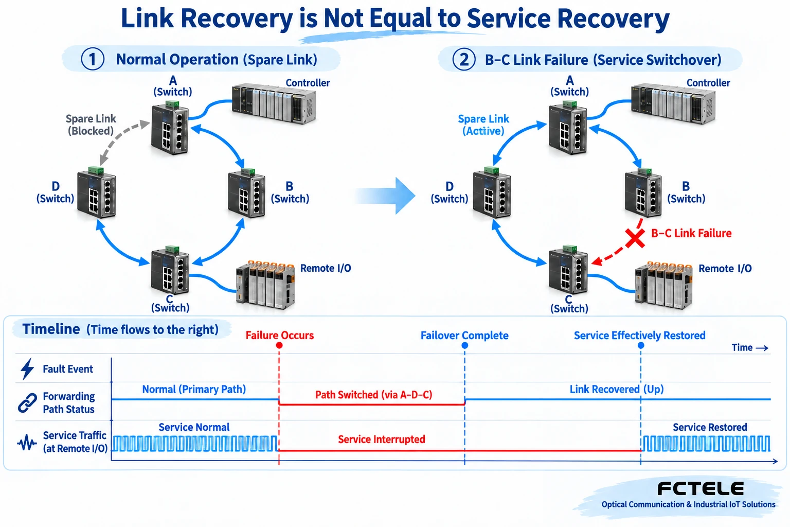
A ring network connects switches into a ring, and then an applicable protocol controls the backup path to prevent service frames from looping endlessly. During a drill, it is necessary to confirm the blocking location under normal conditions, and then perform a controlled fault operation on a specified link or node. After a link break, the backup forwarding path can be released; topology recovery, ports re-establishing connections, and the application obtaining valid data again may not happen at the same time.
Therefore, recovery time should first define the start and end points. For example, from the occurrence of the fault to the remote controller receiving the first service message that meets the requirement, and from unplugging the cable to a certain port turning green, are different indicators. The application may have retry, timeout, or session re-establishment processes, and the sampling interval of the test equipment also affects observation accuracy. Do not directly treat a time number in protocol documentation as the service recovery commitment for the entire project.
6. Use real services to decide the test combination
Suppose a control cabinet connects both cameras and control terminals. You can first verify normal-temperature communication, operation under specified environmental conditions, and controlled link switching separately, and then evaluate the conditions that need to be combined. This only explains how a plan is established; it does not claim that a customer has already tested it. Not every project needs to superimpose the highest temperature, maximum traffic, vibration, and all interference at the same time; the combination should have a basis in requirements, device boundaries, and applicable test methods.
When purchasing Feichang Technology equipment, verifiable functions can be found in the corresponding product information. For example, Chinese product page 3422 lists port statistics, system logs, configuration import and export, and management functions such as STP, RSTP, MSTP, and ERPS. This information helps formulate observation and recovery plans, but whether the functions apply to the delivered configuration and how the protocol works with other devices still need to be checked against the manual and actual testing. You cannot infer from one product that all Feichang Technology switches have the same capabilities.
7. After rectification, rerun the same conditions
After a problem is found, first deal with power supply, heat dissipation, connection, and topology abnormalities that have evidence, then adjust queues, priorities, or broadcast limits. QoS is an arrangement of traffic handling priority; it cannot increase output capacity out of thin air, and overly strict limits may also discard normal discovery or control messages. After each rectification, rerun the original conditions with the same measurement range and compare whether the abnormality disappears, to avoid ending the investigation just because a restart temporarily restores service.
The final report should state which device was tested, which versions, how it was installed, what traffic and environmental conditions were used, as well as abnormalities, stop conditions, recovery methods, and uncovered risks. Save configuration backups and raw records for later review after upgrades. This and laboratory certification reports each have their own purpose: field results serve the current system and cannot be extended on their own into certification conclusions for an entire product category. To understand the scope of standard testing, you can also read Interpretation of Immunity and Temperature Test Reports.
Verification materials:Feichang 3422 Product Details;IEC 60068-2-2:2025 Public Scope Description. The images are general mechanism illustrations, not actual product photos, measured waveforms, or construction wiring diagrams.
Translated from the Chinese technical article. Source first published: 2025-02-13. Source last revised: 2026-10-13T17:37:33+08:00. Read the Chinese source
