


When troubleshooting an E1 optical modem, first distinguish between “a single input failure” and “multiple services interrupted together.” A single tributary, the common multiplexing section, the optical link, and the remote device each have different scopes of impact. First record alarms at both ends, interface configuration, and fault direction, then use a compatible transmission test set and approved loopback tests to narrow down the scope. This article addresses E1 digital transmission and does not replace interface diagnostics with video snow, Ethernet port LED status, or arbitrary restarts.
1. Where are the tributary and aggregate paths respectively
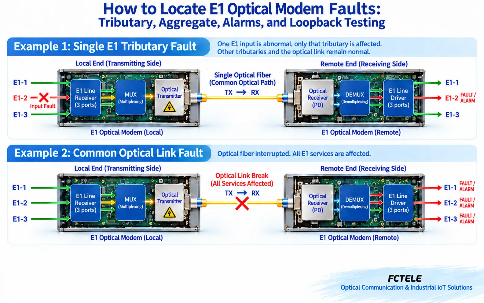
E1 is a 2.048 Mbit/s digital interface. Multiple E1 signals enter the device from their respective electrical ports, go through line reception and multiplexing, and are organized onto a common optical line; the remote optical reception and demultiplexing then restore each tributary to its corresponding port. The tributary is like each individual entrance, and the aggregate is the shared transmission part for multiple services. This analogy is only for understanding the scope and does not mean that all devices have the same multiplexing structure.
When one E1 external cable or input source fails, other tributaries may still work normally. If the common power supply, optical line, or multiplexing section is abnormal, multiple services may be affected. Only “some telephones are not working” is not enough to directly determine a tributary fault; you also need to check call routing, signaling, and the actual bearer relationship. Only by mapping services to E1 ports one by one can you avoid checking the wrong channel.
2. Record the Fault Direction and Time First
Record which end is transmitting, which end is receiving, which channel is abnormal, which adjacent services are normal, and whether construction, power outage, or configuration changes occurred before the abnormality. Recording at both ends simultaneously is more reliable than looking at only one side. A unidirectional error means you should focus on the transmit, receive, and intermediate connections in that direction, but this cannot rule out shared power or clock problems.
Take a hypothetical scenario as an example: among three E1 channels, only the second channel has an alarm, while the other two channels and the optical link remain stable. Prioritize checking the second channel’s signal source, cable, wiring position, configuration, and port, rather than immediately replacing the entire optical modem. If all three channels are interrupted together, then check common alarms, power supply, line, and multiplexing conditions at both ends. This example is a test sequence, not a conclusion without instrument verification.
3. Alarms are clues, not names of damaged parts
LOS means loss of signal, LOF means loss of frame alignment, and AIS is an alarm indication signal; different interface layers and vendors may display them differently. LOS at an electrical E1 port does not necessarily mean the fiber is broken, and receiving AIS does not necessarily mean the local receive board is faulty. The remote end may pass upstream fault information over, so it must be interpreted together with the alarm source and direction.
First read the indicator meanings and alarm objects in the device manual, then observe the continuous state, occurrence time, and recovery sequence. For error counts, first save the cumulative value, then observe the current increment using the difference before and after; if the instrument or device supports clearing, you should also keep a record first and operate according to maintenance regulations. A very large historical cumulative number cannot by itself prove that errors are still continuously occurring now.
4. Check the Electrical Interface, Framing, and Clock Item by Item
Confirm that the 75Ω unbalanced or 120Ω balanced interface matches the cable and connector, that receive pairs with transmit and transmit pairs with receive, and install according to the actual terminal definitions. Mechanical compatibility of connectors does not guarantee suitable impedance. Shielding and grounding should follow the site design, and temporary short cables should not be treated as a permanent engineering solution.
Check line coding, framed or unframed mode, CRC settings, service mapping, and timing source. Transparent transmission devices may not process certain upper-layer parameters, and the test set must still be set according to the interface being tested. If the two ends interpret the service differently, it may appear as having a signal but not synchronizing. An improper clock source may cause problems such as slips, and increasing optical power cannot solve all digital interface errors.
Feichang Technology FCP-E8 eight-channel E1 PDH optical modem The page lists configurations for 1 to 8 E1 channels and optional Console management. On site, verify the actual number of ports and whether the management option is installed; do not treat “optional” as already installed. Loopback positions, alarm meanings, and optical port parameters are still subject to the delivery manual for that specific device.
5. Why loopback testing must specify the location
Loopback causes the test pattern to return at a specified location, and the test set compares the transmitted and received content to determine whether the covered section is working normally. Near-end interface loopback, internal device loopback, and remote line loopback include different paths. A single loopback pass only indicates that the part covered by that setup and test condition passed; it cannot prove that all remote services are normal.
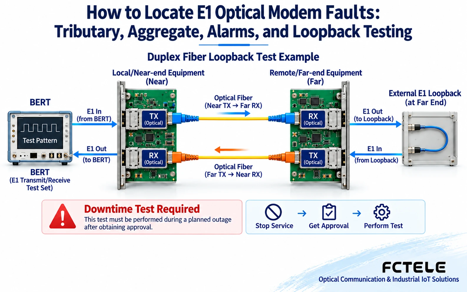
Before testing, obtain service maintenance approval, save the configuration, and confirm a compatible test port. Specify the test direction, pattern, duration, interface conditions, and pass criteria; operate according to the functions supported by the model and do not copy commands from other vendors. Loopback changes the service path, so do not insert a loopback plug arbitrarily during live calls. After testing, remove the loopback, restore the original wiring, and perform an actual service retest to avoid a situation where the device “tests normal” but the service is still looping.
6. How to Combine Optical Path and Replacement Testing
Measure the transmit and receive power in the relevant directions separately and compare them with the allowable range for the actual model; insufficient power, overload, endface problems, and pairing errors should all be considered. When using instruments, set the matching wavelength and adapter, and do not look directly into the optical port. If measurement requires breaking the fiber, it will affect the corresponding service, so first confirm the window and recovery steps.
Use known-good patch cords, ports, or spare devices that are compatible in specifications, version, and configuration, and replace only one factor at a time. Removable modules do not necessarily support hot swapping. If the problem recovers after a restart, save the previous alarms and continue checking factors such as power supply, environment, and configuration; do not directly claim that some integrated circuit’s “data is scrambled.” Repeated resets will lose important evidence and may expand the service impact.
7. Close the Loop from Emergency Recovery to Acceptance
First restore the approved backup path, then arrange root cause location. The handover record should include port and patch panel positions, normal parameters, abnormal direction, alarm sequence, replacement actions, and test results. Verify all affected tributaries, other normal tributaries, actual call or data services, and configuration persistence. If the fault does not recur, clearly write down the observation conditions and do not treat a short-term pass as a permanent solution.
References:Cisco E1 interface troubleshooting materials Used to understand interface layering, not as proof of Feichang Technology commands or functions. The illustrations are general mechanism diagrams, not actual measurements or product certifications; formal testing is based on the actual model manual.
Translated from the Chinese technical article. Source first published: 2019-12-13. Source last revised: 2026-10-13T17:22:03+08:00. Read the Chinese source
