


Evaluating the manufacturing quality of optical transmission equipment cannot rely only on descriptions like “professional production” or “high-speed stability.” What really needs to be checked is: whether the delivered interfaces and signals match, whether optical-electrical conversion and service recovery can be verified by testing, and whether the same batch and the next batch of equipment have clear version and traceability records. Starting from general working mechanisms, this article explains how buyers can ask verifiable questions, without treating an illustrative production process as tests that a particular factory has already completed.
First lock down the product object, then quality has a basis for comparison
“fiber optic transmission device” covers many kinds of services: video, telephone, serial port, digital I/O, or multi-service combinations, and their input and output circuits differ. For example, SDI video uses a high-speed digital sequence, analog video requires corresponding sampling and recovery, and telephone also involves interface pairing and signaling. Before comparing two suppliers, the number of channels, signal format, direction, optical port configuration, power supply, and installation conditions should be written into the same requirement; otherwise price and test results do not share the same premise.
Samples, quotations, datasheets, and deliverables must correspond to a complete model and version. When only a series name is available, ask for a supplementary option list, including interface boards, optical modules, power supply, and software. A series supporting a function does not mean every shipped configuration includes that function; the same enclosure does not mean the service boards inside are identical. Only by writing these conditions clearly can manufacturing consistency be distinguished from choosing the wrong configuration.
How optical-electrical conversion works, and which details can affect quality
In general digital optical transmission, the input circuit first receives or organizes the electrical signal according to the corresponding service, and the optical transmit circuit turns the data into light intensity that changes over time. The optical fiber carries these changes, the detector at the receiving end converts light into current, and after amplification, decision, and applicable clock recovery circuits, data is formed for the later stages, finally output by the service interface. Power supply stability, clock quality, interface electrical conditions, and the optical channel can all affect the entire path.
The “amplification” here mainly refers to electrical signal processing at the receiving end, and it cannot be used to claim that every optical transmission device has a built-in optical amplifier. Complex trunk equipment may use digital signal processing or forward error correction, but these are not universal configurations for all simple point-to-point devices. When asking a supplier, focus on the actual functions of this model and the verification records that can be provided, and do not replace evidence with a string of advanced technology abbreviations.
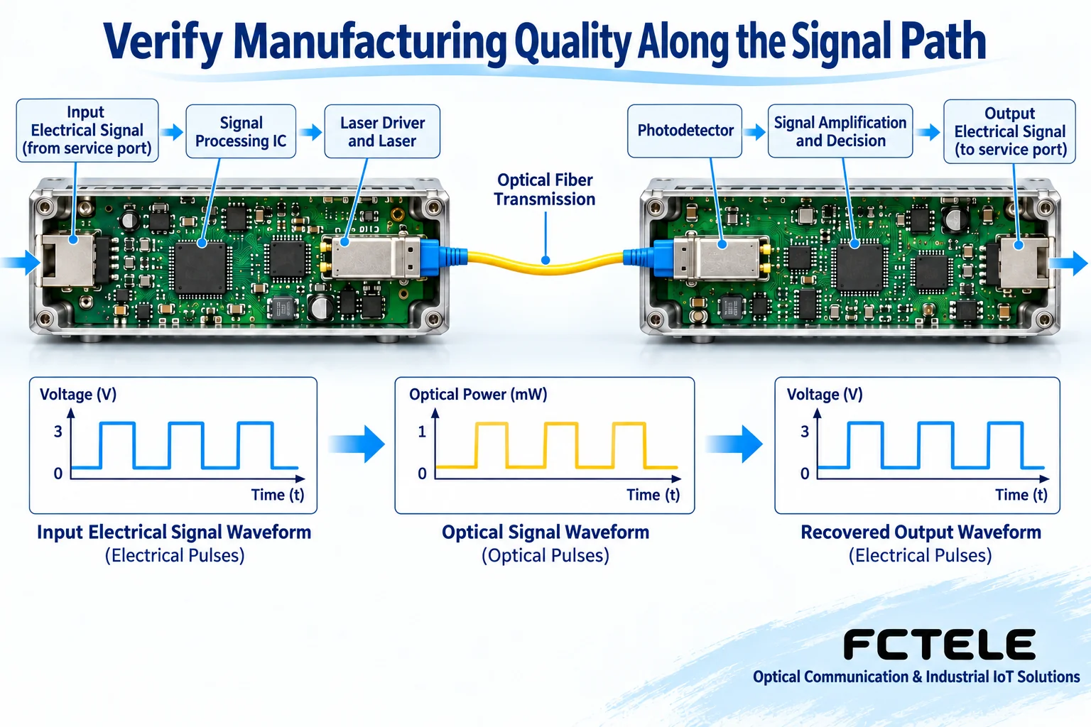
Assembly inspection is not just “the light turns on”
When inspecting connectors, soldering, and mechanical installation, there should be acceptance criteria corresponding to the model. Loose interfaces, unreasonable stress, blocked heat dissipation paths, or power wiring that does not meet requirements may only be exposed after transport, temperature changes, or operation. Buyers can request inspection items, judgment methods, and nonconforming handling records, rather than giving conclusions by visually disassembling the unit on site. When internal inspection is involved, it should be carried out by authorized personnel according to procedures.
Contamination on the optical port end face increases loss or reflection, and both assembly and packaging should include cleaning and protection arrangements. When receiving goods, check the protective caps, labels, and interface condition, and use suitable tools during maintenance. Do not replace the fiber cleaning process with ordinary wiping habits, and never look directly at an end face that may be carrying light. Equipment operating on a clean short link is only a basic check; it has not yet proven that the site link and all services pass acceptance.
Connect test conditions, results, and equipment numbers
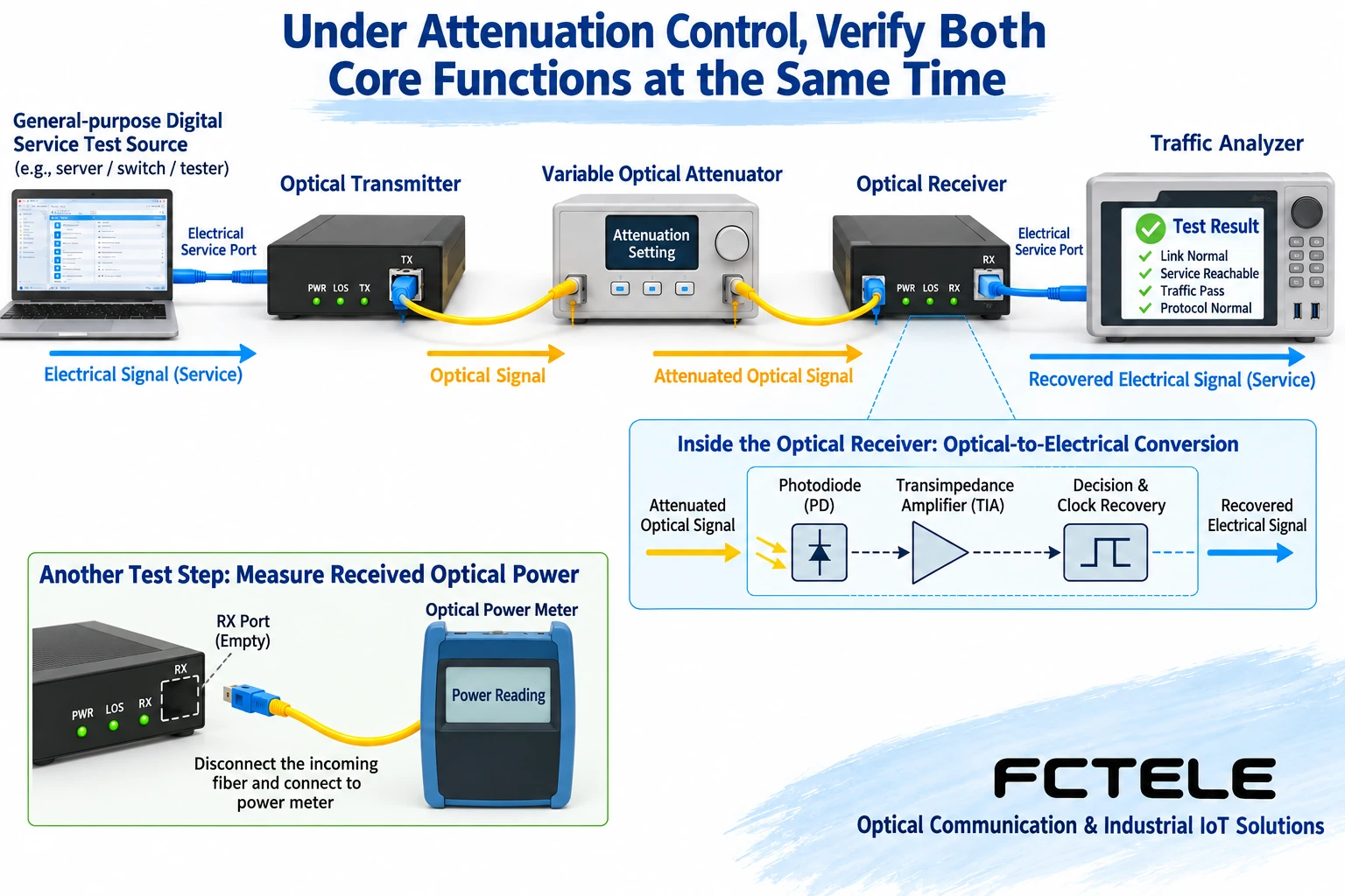
Optical channel testing should record the optical port configuration, transmit and receive conditions, test link, and instrument information. When applicable, a variable optical attenuator can be used to observe receiving performance within a specified range; for digital services, a matching test source and analyzer should also be used to judge whether the data is correct. Optical power is an indicator of signal strength and does not directly tell us whether every bit of data is correct. Meeting an optical power target cannot replace service quality, and test instruments for different formats cannot be used interchangeably.
For interfaces where bit error testing can be performed, the rate, pattern, observation time, and counting rules must be specified. Observing zero errors only means that no errors were detected during that time and under those conditions; it does not prove that there will never be errors in the future. For services such as video and telephone, verify image, call, signaling, or interface functions according to the corresponding methods. Multi-service equipment should load all channels to be delivered at the same time, to prevent single-channel testing from hiding problems in the combined configuration.
Environmental and recovery tests must correspond to actual use conditions
If a project involves temperature changes, power supply disturbances, or frequent reconnections, the applicable test conditions and service observation methods should be agreed upon. The sample model, options, operating state, and criteria in an environmental test report need to correspond to the purchased equipment. Storage temperature and operating temperature are different, and the test chamber setting is not equal to the internal temperature of the product; a photo of test equipment cannot prove that the product has reached a certain environmental rating.
Recovery testing must also be specific. For example, in an approved test environment, simulate fiber breakage and reconnection, record which channels recover, whether manual operation is required, whether there are abnormal alarms, and the actual recovery performance at the service end. Do not infer from “the link light turns on again” that telephone and video are already normal. Power-off, fiber unplugging, or loaded experiments on production equipment should be arranged on an isolated test bench or within an approved window, to avoid affecting systems in operation.
Batch traceability, so the next purchase can still be checked
The purpose of traceability is to find the relevant configuration and test records when an abnormality occurs. At a minimum, it should be possible to associate the equipment serial number, production batch, hardware and software versions, optical port options, and factory inspection results. If the supplier changes key components or versions, it should explain the scope of impact, alternative verification, and compatibility arrangements. Buyers should also keep the sample acceptance configuration, to avoid later orders only saying “same as last time” without a checkable basis.
For example, if the sample uses one optical port configuration and passes testing, but the batch delivery changes to another option, this does not necessarily mean the equipment has a manufacturing defect, but the original power budget and pairing conclusions cannot automatically be carried over. First identify the difference, then perform the corresponding verification, before deciding to accept, adjust, or return. When the delivery list, version description, and test numbers match, it is more effective at reducing later disputes than a general “quality assurance.”
Put the configuration characteristics of Feichang Technology products into the acceptance form
Feichang Technology FCV-V4T/R product page It provides a modular configuration approach with 4 video channels and optional auxiliary services, and lists desktop and rack-mount forms. For projects requiring a combination of video, data, or telephone, this configuration method helps determine interfaces according to requirements; during acceptance, the actually assembled service boards, direction, and port definitions must still be confirmed, and optional items cannot be treated as all standard.
The video interface on that page lists PAL, NTSC, and SECAM analog video formats, and the BNC interface of this device cannot be treated as an SDI input. The problem in the original text of mixing manufacturing technology with all services should be resolved through accurate model and signal objects. Ultimately, forming an acceptance table in which configuration, assembly, optical channel, service, environment, and traceability records correspond to one another is an executable quality verification.
For the impact of optical power measurement and end face condition on results, refer to Cisco optical power measurement explanation; its router commands and model specifications are not functions of Feichang Technology equipment.
Translated from the Chinese technical article. Source first published: 2024-07-10. Source last revised: 2026-10-13T17:37:33+08:00. Read the Chinese source
