


The hardest fiber optic transmission device problems to troubleshoot are often not continuous link failures, but “it works after a restart, then fails again after a while.” The goal of maintenance is not just to make the indicator light come back on, but also to leave evidence that can explain the fault. Put power supply, optical path, services, and environment on the same timeline, then use controlled tests to verify your guesses, so you can gradually find the conditions that cause intermittent faults.
1. Restore Services First, but Preserve the Evidence
When a fault occurs, first confirm the scope of impact: whether both ends are online, whether all services are down or only a single channel is abnormal, and whether other equipment at the site restarted at the same time. For production systems, restore services according to the existing emergency plan, and do not extend downtime without authorization just to diagnose. But if conditions allow, before restarting, clearing alarms, or restoring factory settings, first save alarm times, indicator light states, logs, configurations, and wiring photos.
This information is easily overwritten by restart or reset operations. Just writing “there was a problem in the afternoon” is not enough to align with other systems; you should record the date, time, and whether device clocks are consistent. For devices that cannot synchronize clocks, note the deviation from standard time. Keep the original records, then make a separate analysis copy, and do not treat a few filtered lines as the complete event process.
2. What a Normal Baseline Is
A baseline is a set of reference records from when the system is running normally, not a uniform passing number copied from the internet. It should include the models and versions at both ends, service type, configuration, power supply method, fiber path, received optical power, readable error statistics, and site temperature, etc. Only record items that the device actually supports; do not present the monitoring capabilities of other models as your own functions.
Optical power should be compared with the receiver’s allowed range, and at the same time observe changes relative to the original normal state. The same reading may have different meanings on different receivers; too weak and too strong can both cause problems. If optical power is normal but a certain E1 tributary reports errors, you still need to look further at the electrical interface, clock, or frame settings; optical power is not a substitute indicator for all service quality.
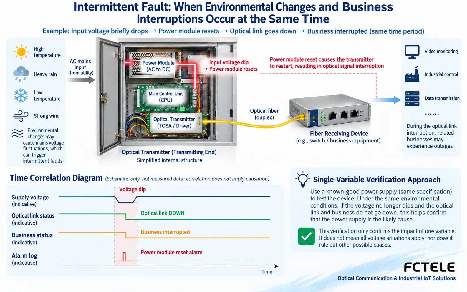
3. Use a timeline instead of guesses to connect faults
For example, for occasional link failures at night, you can match the fault time with cabinet power supply, camera fill light startup, device temperature, and other load actions. This is a troubleshooting example and does not mean the fill light must be the cause. Finding that two events occur at the same time only means they are worth further verification; they may also both be affected by the same upstream condition.
If the voltage at the device input drops when the load changes, judge according to the model’s allowed values and measurement methods. Do not test only a no-load adapter and conclude that the power supply is fine. Poor contact, cable voltage drop, or insufficient power margin may all need to be checked. Mains-side checks and live measurements must be performed by qualified personnel. Without authorization, do not directly connect field equipment to a power source of another voltage for testing.
Temperature is also a clue, not a conclusion. Cabinet temperature, case temperature, and component temperature are not exactly the same; state the measurement location clearly. First check ventilation, dust accumulation, installation spacing, and nearby heat sources, then evaluate according to equipment specifications. Do not judge damage just because the device feels hot, and do not use the words “industrial grade” to replace actual operating temperature and heat dissipation conditions.
4. Understanding Error Counts and Trends
The cumulative total error count may include events from a long time ago. More valuable is how many new errors occurred within a fixed observation interval, whether services were affected at the time, and whether the counter reset to zero after a restart. First save the original value, then record the start and end times and the difference; numbers from different observation durations cannot be directly compared. If the device does not have the corresponding counter, use available alarms, service tests, and external instruments, and do not invent monitoring readings.
A gradual change in received optical power rising at the same time as an increase in errors suggests the optical path is worth checking, but you still need to rule out instrument settings, wavelength selection, connector condition, and measurement repeatability. A single fluctuation cannot directly lead to a conclusion about laser lifetime. During measurement, record the instrument model, settings, and measurement point, so that the next retest can be done under the same conditions.
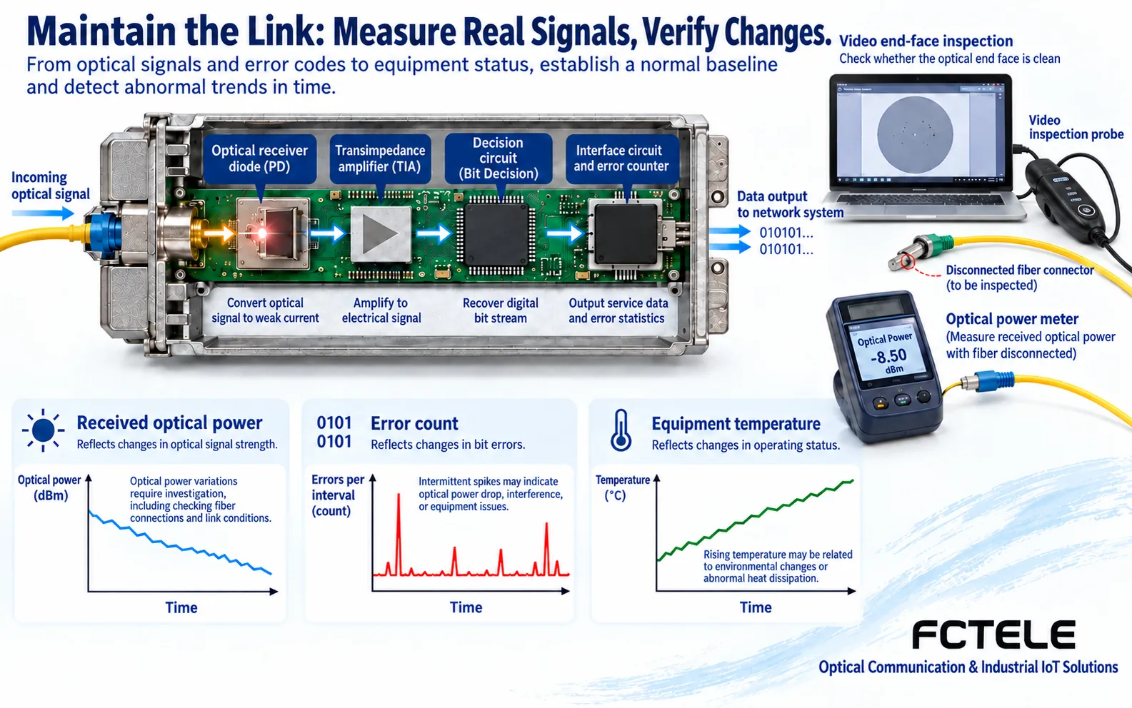
5. Check Fiber End Faces in the Correct Order
Do not treat “unplug and plug it back in” as a cleaning method. First stop the relevant services according to safety requirements, use a suitable endface inspection tool to determine contamination, then use a cleaning tool matched to the connector, and inspect again. Contamination may transfer during connection, and a cleaned endface cannot be assumed to stay clean. Ordinary cotton swabs, casual wiping, or unconfirmed solvents should not replace proper tools.
Do not look directly at optical ports or bare fiber endfaces, and do not judge that there is no light just because you cannot see a bright light. When measuring optical power, confirm the wavelength and instrument settings, and record the service impact that disconnecting for measurement will cause. When organizing patch cords, avoid excessive bending and squeezing, and keep line labels; do not unplug multiple unlabeled connectors at the same time just to troubleshoot one line.
6. Replacement and Upgrades Require Controlled Variables
Replacing items one by one with known-good and compatible power supplies, patch cords, or devices can narrow the scope, but each time you must record what was replaced, when it was replaced, and whether the fault reappears under the same conditions. If you replace three things at once, even if it recovers, it is hard to know the real cause. Spare equipment also needs to be checked for service interfaces, wavelength combination, optical power range, and configuration; looking the same does not mean it can be directly swapped.
Firmware upgrades or factory resets are not a universal first step. First back up the configuration, confirm the manufacturer’s applicable version, upgrade path, and rollback conditions, then arrange a test window. For tests that change service paths, such as E1 loopback, after finishing you must remove the test state and recheck settings at both ends. Do not treat a “pass” in test mode as production service already restored.
The Feichang FCP-E8 product description lists multiple E1 transmission and optional Console and other interfaces; the FCP-F4pD8 description also includes corresponding network management configuration options. During maintenance, check the actual ordered configuration and readable items of the device in hand, and use existing management capabilities to save status, rather than assuming all fiber optic transmission devices can output temperature, optical power, or complete logs. When monitoring items are missing, you can supplement with standardized external measurement records.
7. Recovery Acceptance and Follow-Up Handover
After recovery, first verify services: check video images, control actions, E1 communication, or other carried services separately. Then observe whether alarms disappear and whether errors continue to increase, and cover the time or load conditions when faults were originally likely to occur. The observation duration is set according to service risk; do not write a fixed number of minutes that applies to all sites.
The handover record should at least explain the fault scope, occurrence time, normal baseline, actions taken, final configuration, and any still-unexplained abnormalities. If only temporary recovery is possible, clearly state “cause not yet confirmed,” arrange follow-up checks, and do not treat the absence of recurrence as a permanent solution. If the same tributary fault continues to occur, you can turn to E1 tributary and aggregate channel troubleshooting; for video and integrated services, refer to Five-category fault sectional inspection.
Reference Notes: For end face handling, refer to Fluke Networks endface inspection principles; for product information, refer to Feichang FCP-E8 and FCP-F4pD8. The illustrations are general mechanism diagrams, not field measurements, physical photos, or performance certifications.
Translated from the Chinese technical article. Source first published: 2025-02-11. Source last revised: 2026-10-13T17:22:03+08:00. Read the Chinese source
