


When troubleshooting a fiber optic transmission device, first distinguish the symptom: no image, image interference, control failure, single branch fault, and optical path abnormality. The corresponding check points are not the same. First confirm whether the device carries analog video, SDI, Ethernet, or E1 services, then use measurement and substitution to locate the problem. Do not apply the same set of indicator light meanings or blindly replace boards.
No image: check input and output separately
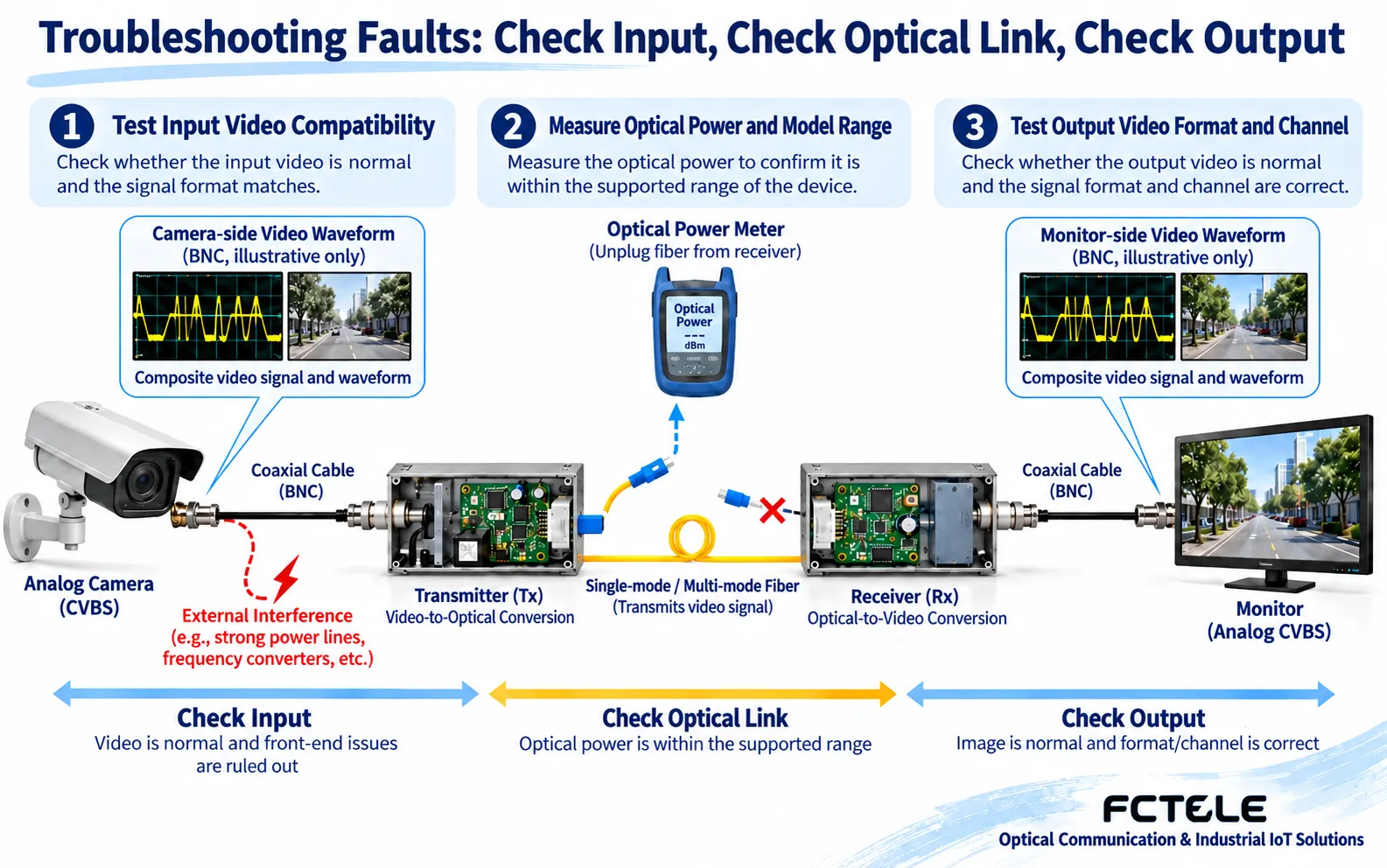
A video link involves at least a camera, input cable, transmitter, optical fiber, receiver, output cable, and display device. The first step is to check whether the power supply meets specifications and whether the channel is connected correctly. The second step is to verify the output of the front-end camera. You can use a compatible tester or a known-good receiving device to test against it, avoiding misjudging a camera with no signal as a broken fiber optic transmission device.
The receiver may have an optical link but still no usable video. Analog CVBS, SDI, and IP video use different interfaces or protocols. They cannot be interchanged just because they all have BNC connectors or all are called “video fiber optic transmission devices.” Confirm the format, resolution, and supported range. If the input is valid but there is no output signal, then check the port, optical path, and channel settings segment by segment. Indicator lights are clues, but service-layer testing is still required.
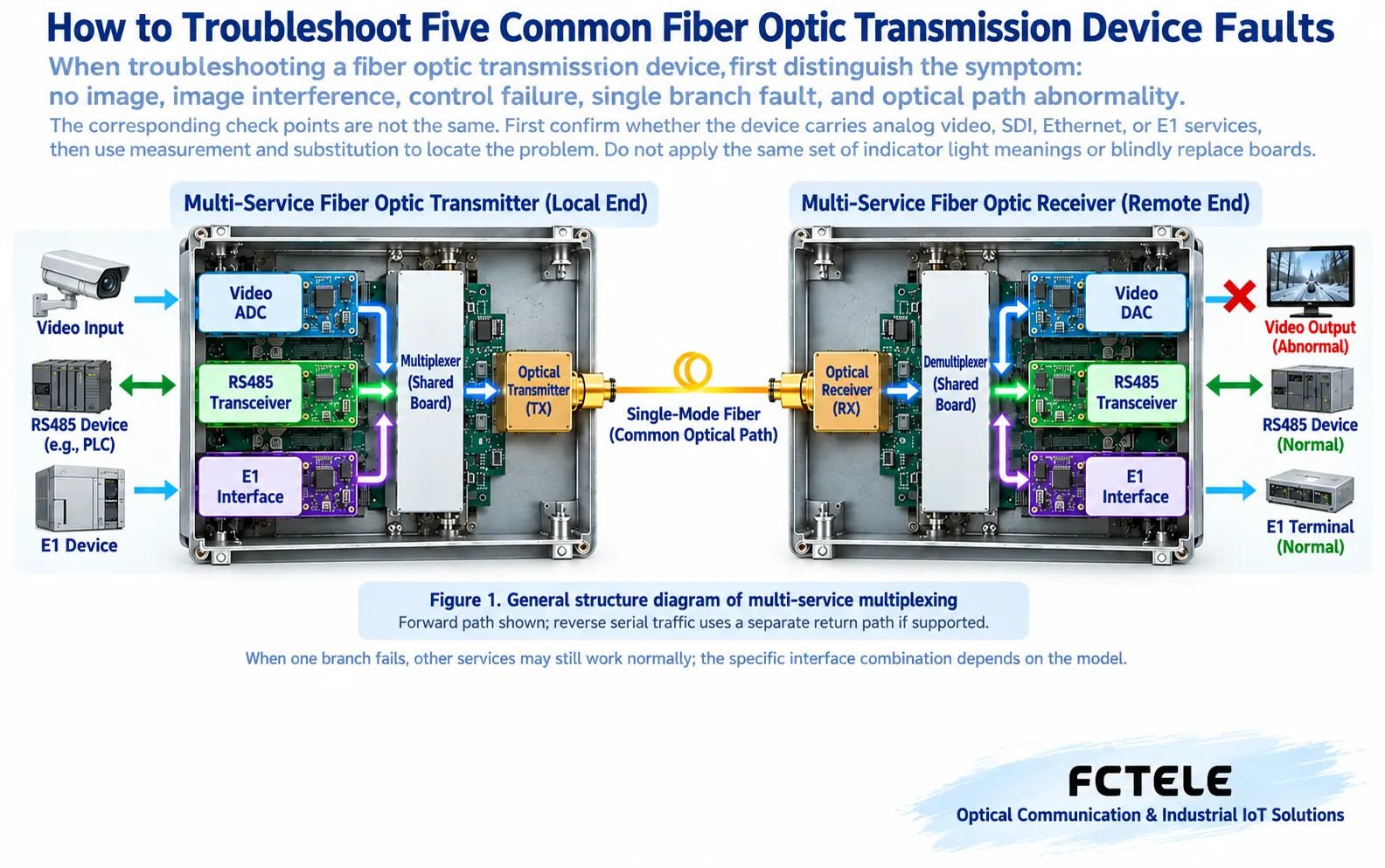
Image interference: first identify the signal type
When analog video shows horizontal bars, snow, or ghosting, check the impedance matching of the coaxial cable, connector contact, shielding, and power interference. Ground potential differences can also cause image abnormalities. Handling should follow the on-site grounding design; protective grounding should not be removed arbitrarily. Connecting a known-good short-distance video source to the transmitter is an effective way to distinguish between the front-end cable and the subsequent link.
Abnormalities in digital video or network video may appear as dropped frames, mosaic, black screen, or decoding errors, and may not show analog snow. At this time, check bit errors, link reconnection, packet loss, uplink load, and receiving device compatibility. Connector contamination and insufficient optical power can also cause intermittent faults. Do not rule out the optical path just because “it works during the day.”
You can see the image but cannot control
Video and pan-tilt control are usually different service channels. Check whether the controller actually sends commands, then verify the RS-232 or RS-485 electrical interface, terminal definitions, baud rate, data format, device address, and control protocol. The definitions of A/B letters may differ between devices. Check according to the manual, not by wire color.
RS-485 requires consideration of bus topology, termination matching, and reference potential. Long star branches, multiple masters transmitting simultaneously, or incorrect termination configuration can all cause occasional control failures. Changing one item at a time and recording the results makes it easier to find the cause than modifying address, baud rate, and wiring all at once.
Only one service branch is lost
A fault in one branch of a multi-service device does not necessarily mean the entire optical link is down. Check the corresponding input source, channel mapping, interface board, and service alarms. E1-type services also require checking framing mode, clock, and line status. Loopback testing changes the service path and should be performed during an approved maintenance window, and it must be clear whether it is a local interface loopback, internal device loopback, or remote loopback.
A known-good interface or device of the same model can be used for substitution testing, but version and configuration compatibility should be verified. Some modules do not support hot swapping. Do not treat “removable” as “can be replaced while powered.” After a single channel recovers, also confirm that other branches have not been affected.
Optical path alarm: measurement is more reliable than guessing
First record the alarms and received power at both ends, then check jumpers, connectors, splices, and optical cables. If the transmit power is normal but the far-end receive power is low, it indicates that intermediate loss needs to be checked. If power is sufficient but synchronization still fails, then also verify wavelength, rate, and pairing compatibility. Short jumper testing can also fail due to excessively strong received power. Do not simply assume that shorter distance is always better.
Endface cleaning should follow the sequence of inspect, clean, and inspect again, using dedicated tools to avoid residual fibers from ordinary cotton. Do not look directly into optical ports, and do not arbitrarily unplug fibers during production services. For contamination and cleaning, refer to Fluke Networks fiber endface inspection materials. After recovery, save the fault symptom, measured values, corrective actions, and retest results to form a reusable maintenance record.
First establish a test baseline that will not cause confusion
“Device startup” and “service normal” are two separate acceptances. During startup, confirm that power supply, terminals, alarms, and configuration can remain stable. Service acceptance must also prove that the input source, far-end output, control return path, and actual load are all normal. If the power light is on but startup repeats, it may come from power supply drop under load, poor plug contact, or internal device problems. Save the symptoms and logs, then test against a power supply with matching specifications during a maintenance window. Do not treat a brief recovery after restart as the root cause being resolved.
Before measurement, prepare the device model, hardware and firmware versions, interface configuration, optical port type, and normal baseline. For each operation, write down which factor was changed, how long it was observed, which channels recovered, and which remained abnormal. If you first unplug the fiber, then replace the power supply, and then restore factory settings, even if it finally recovers, it is difficult to determine which step produced the effect. Restoring factory settings will clear the configuration, so you must back up first and obtain maintenance approval.
Output and branches also require independent acceptance
For analog video, verify image, synchronization, and channels. For digital video, use a compatible receiving device to observe format and errors. For serial ports, verify specific commands and responses. For E1, check line, framing, clock, and error counts. Do not treat Ethernet CRC, video lock, and E1 alarms as the same counter, and do not assume that all fiber optic transmission devices have a network management interface.
When a single E1 branch or group path fault occurs, you can continue to read E1 branch and group path troubleshooting. When you need to back up configuration and establish trend records, see fiber optic transmission device maintenance baseline and evidence retention. These two types of problems require independent interface testing and maintenance methods. Do not replace boards based only on video troubleshooting conclusions.
Boundaries of multi-service devices
Feichang Technology FCP-F4pD8 dedicated optical transmission equipment lists serial interface and switch quantity configurations. On site, terminal definitions, directions, and rated conditions should be saved separately for each service, avoiding skipping control and load-side acceptance just because the optical path is normal. This article only explains the layered method and does not generalize the optional functions of this model to all fiber optic transmission devices.
Documentation note: The illustrations are general principle diagrams, not actual product cross-sections, on-site measurements, or certification proof. Interfaces, power supplies, firmware, and safety conditions are subject to the actual model manual. Strong current, live measurements, lightning protection, and grounding rectification should be handled by qualified personnel.
Translated from the Chinese technical article. Source first published: 2019-12-11. Source last revised: 2026-10-13T17:22:03+08:00. Read the Chinese source
