


“Fiber optic transmission equipment” is a general term for optical transmission devices, not a fixed interface. Video, E1, telephone, serial port, and dry contact devices may all use this name, but they process different signals. When encountering problems such as inability to connect, no image, or backup power not working, first confirm the actual model and service, then check the electrical interface, optical port pairing, and power supply. This article explains confusing usage issues one by one to avoid wiring based on connector appearance or generic values from old articles.
1. First, clarify which signal you want to extend
The device’s input determines how it works. Analog video fiber optic transmission devices receive continuously changing video voltage; digital transmission equipment receives already-encoded data; dry contact fiber optic transmission devices detect contact or level states. The transmitter encodes the corresponding information and converts it to light, and the receiver restores it to the corresponding interface. Fiber optics solves the transmission medium problem; it will not automatically change a telephone into Ethernet, nor will it convert E1 into video.
Prepare an interface list: signal source, transmitting port, receiving port, remote device, direction, channel number, and required signal format. Port names and manual definitions are more important than “it can be plugged in.” When a device supports multiple services, each service still has its own input and output conditions, and different terminals should not be cross-tested.
2. Can PDH and SDH be directly interchanged?
PDH is Plesiochronous Digital Hierarchy, and SDH is Synchronous Digital Hierarchy. The difference involves multiplexing structure, clock organization, and management mechanisms. They are not video clarity levels, nor can capacity be judged by appearance alone. A PDH device providing an E1 interface cannot be directly paired with an SDH device on the same fiber just because the SDH device also has an optical port. It is necessary to check the optical line format, rate, service mapping, and equipment matching requirements.
If migrating existing E1 services to another transmission system, first check whether the service is transparently transmitted, how the clock is obtained, and whether port impedance and framing conditions match the existing network. Large rack capacity does not mean it can unconditionally replace small devices; when purchasing, describe the actual service and connection objects at both ends, not just say “replace with a more advanced fiber optic transmission device.”
3. The “2M” in a BNC connector is not a two-meter video cable
In communication materials, 2M usually refers to the E1 2.048 Mbit/s digital interface, not a two-meter cable. E1 can use a 75Ω unbalanced coaxial interface or a 120Ω balanced interface, and the actual port and cable should correspond. BNC is also common for analog video or SDI, but the same connector does not mean the same waveform, rate, and protocol. Do not connect an E1 port to a camera, and do not treat all RJ45 as Ethernet.
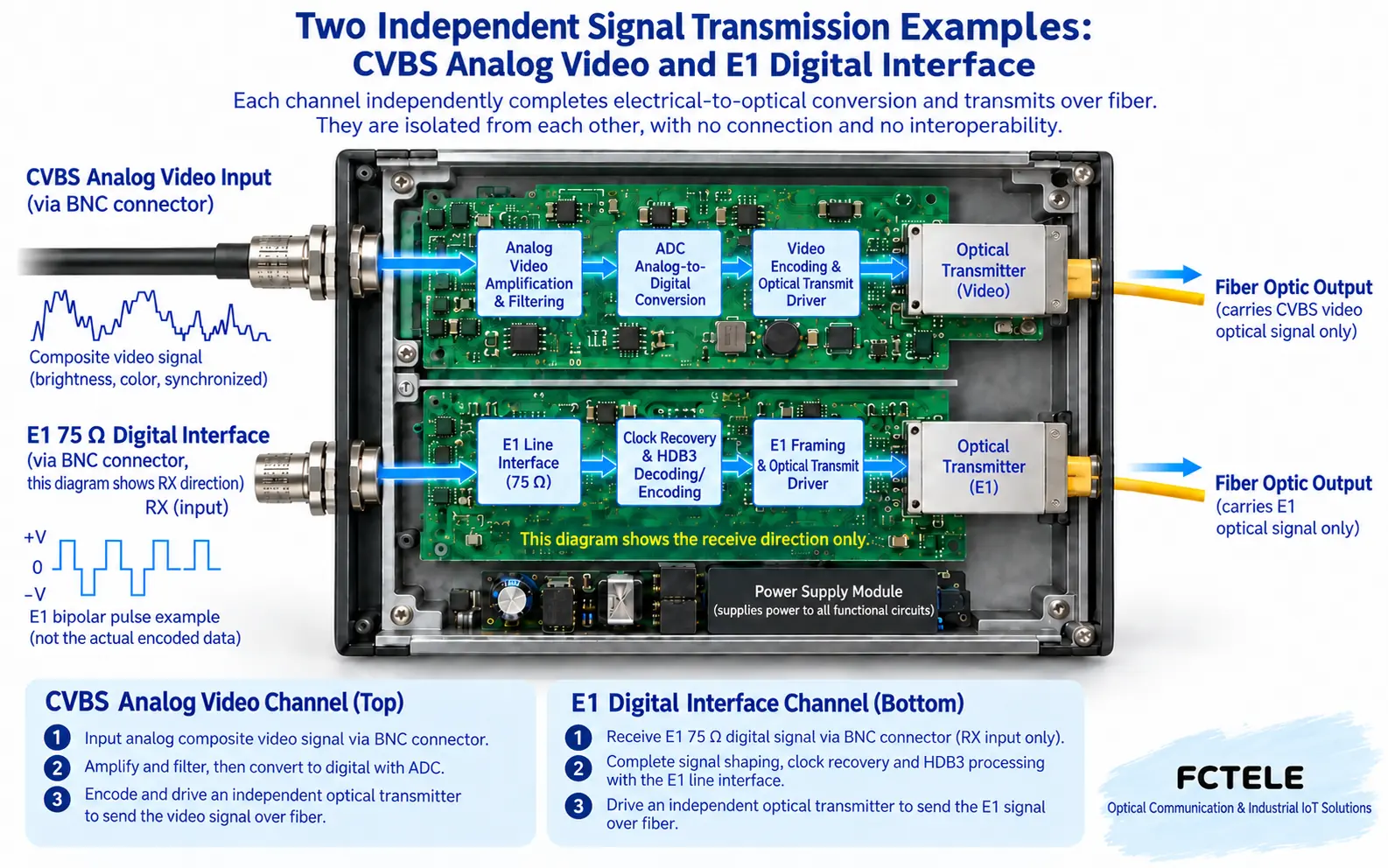
If the original device terminals are not clearly marked, stop and check the wiring diagram. When conversion between 75Ω and 120Ω is needed, use a conversion device that meets the interface requirements, not just a mechanical adapter. Crimping, shielding, and receive/transmit directions should be done according to the device instructions. Do not use temporary short circuits to test interfaces on a running link.
4. What devices are connected at both ends of video?
A typical analog video link is camera output, transmitter video input, fiber, receiver video output, compatible monitor or recording device. Only when the input is valid and the optical link is established can a remote image be obtained. SDI, HDMI, and network video each have different interface and format requirements, and analog video wiring cannot be applied to them. Furthermore, do not directly judge that a board is damaged from a black screen or snow.
Feichang Technology FCV-V4T/R four-channel integrated multiplexed video fiber optic transmission device The documentation provides modular configuration and video/data status indications. Such multi-service solutions should be tested channel by channel according to the actual configuration: first verify the input, then observe the remote output, and finally confirm the independent control channel. The series may offer a certain function as an option, but that does not mean every device is equipped with it.
5. Can dry contacts directly connect to an alarm light?
Dry contacts transmit open, closed, or high/low states. The input may require a dry contact or a specific level; the output may be a relay contact or another electronic output. A dry contact only indicates contact state, not that the device will supply power to a load. Input type, output rated voltage and current, normally open/normally closed, and link-loss state must all be checked separately.
First use an approved low-voltage test circuit to verify the state, then connect the actuating load according to the design. Alarm bells, lights, or contactors may have startup inrush and inductive kickback. When exceeding interface capability, suitable intermediate drive and protection are needed. Do not interpret “has a relay” as being able to connect any power. For control services, refer to RS485 and dry contact troubleshooting.
6. How to choose backup power?
Backup power should cover the entire service chain that truly needs to be maintained, including fiber optic transmission devices at both ends, cameras, or control devices. If the fiber optic transmission device continues to run but the camera has lost power, there will still be no image. AC input devices can be powered by a suitable UPS; DC input devices require a backup system that matches voltage, polarity, load, protection, and conversion conditions.
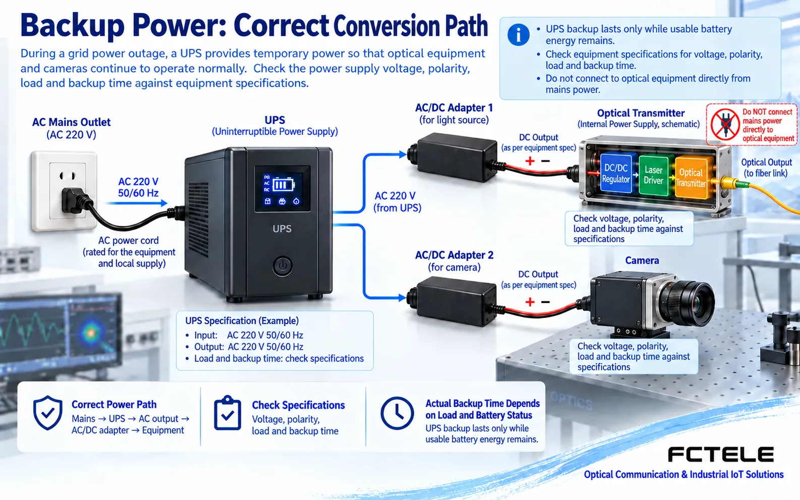
Battery life cannot be judged only by nominal battery capacity. Also consider actual load, conversion efficiency, discharge conditions, temperature, aging, and necessary margin. Different devices may have different inputs. Do not classify by “good device 9V, bad device 5V,” and do not directly connect an unchecked battery to the power port. Perform switching verification within an approved window, and record whether restarts occur and whether each service recovers.
7. How to distinguish network management connection failure from temperature over-limit?
The management channel is used to read status and change configuration; the service channel is used to transmit actual signals. When network management is unreachable but services are normal, first check the management connection, address, permissions, and whether the device supports that method; if services are also interrupted, also check shared power and optical path. Terms such as DCC should be explained in the context of the specific system, and the management mechanism of one telecom device should not be applied to ordinary video equipment.
For temperature alarms, first confirm whether it measures ambient, enclosure, or internal sensor, then compare with the operating range. Check heat sources inside the cabinet, airflow paths, dust accumulation, and ventilation conditions. Do not claim that all fiber optic transmission devices are suitable for 0–50°C. After improving the environment, continue to observe services and alarms; do not judge that the device is permanently normal based on a single cooling.
8. What should be kept after testing and recovery?
Save the actual interface list, power supply version, optical port model, measurements at both ends, test steps, and observation time. First establish a baseline under compatible known-good conditions, then connect to the live link, changing only one factor at a time. After recovery, verify each signal, return control, and power-off recovery one by one; do not replace complete acceptance with “the light is on.”
References and boundaries: Refer to Feichang Technology product documentation and actual delivery manuals. The illustrations are generic mechanism diagrams, not physical cross-sections, measurements, or certifications. Do not look directly into optical ports; strong current and live measurements must be performed by qualified personnel.
Translated from the Chinese technical article. Source first published: 2019-08-05. Source last revised: 2026-10-13T17:22:03+08:00. Read the Chinese source
