


Distinguish point-to-point, star, chain, and controlled ring networks by ports and forwarding mechanisms, and explain the capability boundaries of transceivers and switching devices.
First draw the ports, then name the topology
The basic purpose of a Ethernet fiber media converter is to connect different transmission media. You cannot assume it supports any network topology just because it is labeled “industrial-grade.” The most common one-copper-one-fiber device connects one copper cable segment and one fiber segment; whether it includes bridging, multiple service ports, network management, or loop prevention capabilities must be proven by the specific model. Topology names describe how devices are connected, but what really determines whether a topology can be implemented is each device’s ports and forwarding mechanism.
This article discusses Ethernet services. First list on paper each node’s electrical ports, optical ports, and device model, then use lines to mark each independent link. One optical port cannot connect two ordinary point-to-point lines at the same time, and one patch cord cannot merge multiple independent Ethernet signals just through a connector. When branches are needed, you usually must introduce a corresponding multi-port switching device rather than directly splitting the fiber.
Point-to-point links are the easiest to verify
Two compatible transceivers can connect two Ethernet electrical connections through fiber, or one transceiver can connect to a compatible optical port on a switch at the other end. Dual-fiber wiring should let TX reach the remote RX; single-fiber bidirectional requires paired wavelengths. Each end needs power that meets specifications, and the electrical port rate and optical port conditions must also be checked separately. The long-distance transmission capability of fiber cannot offset incompatibility of electrical ports, modules, or protocols.
During acceptance, first verify a short link, then migrate to the site. Record the fiber type, connector loss, and allowed receive range. If conditions permit, measure optical power and compare it with the model specifications. Then verify bidirectional service, continuous load, and port statistics. Device indicator lights can help locate problems, but they cannot prove that address, application, and bandwidth requirements are all met.
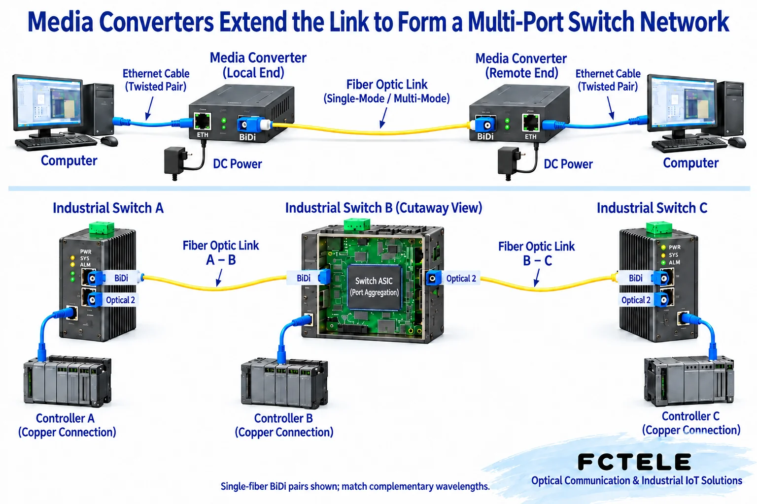
Star topology requires the center node to have aggregation capability
In a star topology, multiple remote ends connect to the center through independent links. The remote ends can be electrical-port terminals plus transceivers, and the center usually needs multiple available optical ports, or multiple transceivers connected to a center switch. The center’s switching function is responsible for sending frames from different ingress ports to the corresponding egress ports. You cannot treat an independent converter with only one optical port as the center for multiple remote ends unless the product truly provides the corresponding multi-port function.
This method facilitates branch isolation: a fault in one remote link usually does not directly cut off other independent branches. However, the center device, power supply, or common uplink can still become a common failure point. The number of center ports, shared uplink bandwidth, and power supply should be calculated according to the business. Feichang Technology transceiver product information can be used to check remote media conversion combinations, while center aggregation should separately check the switch’s port and management capabilities. You cannot use the same device name to replace these two types of tasks.
Chain nodes must be able to continue forwarding
A chain topology connects nodes in sequence. If an intermediate node must connect both the preceding and following optical links and also connect a local terminal, it needs the corresponding number of optical ports and forwarding capability. A basic one-copper-one-fiber transceiver does not have enough interfaces to complete these connections at the same time, and you cannot add a physical optical port just through software settings. Devices that support this topology may be switches with multiple optical ports or devices that explicitly state chain capability.
A chain saves certain cabling paths, but it aggregates downstream traffic onto upstream links. An upstream power failure, cable break, or forwarding fault may affect multiple downstream nodes. When planning, calculate the aggregated traffic for each segment, record the affected range, and consider whether bypass or backup paths are supported by the product. Do not equate “chain” with “unlimited cascading.” Ports, service load, fault range, and recovery requirements all have practical limits.
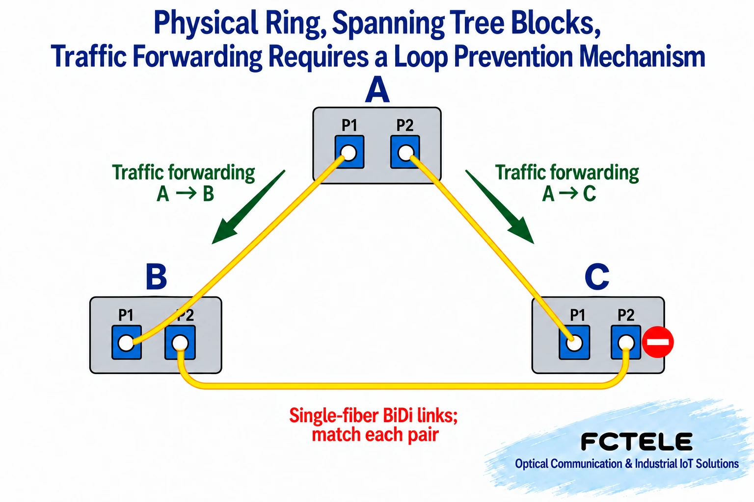
A physical loop must have a controlled mechanism
Connecting into a closed circle is only a physical loop; it is not equal to a working redundant ring network. Ethernet broadcasts and some unknown unicasts may circulate repeatedly in an uncontrolled loop, causing storms and address learning abnormalities. Spanning Tree Protocol avoids Layer 2 loops by selecting forwarding paths and keeping some paths in a non-forwarding state; other ring mechanisms also have their own conditions. Before connecting the backup line, you must confirm the support and configuration of all relevant devices.
In the three-node example in the figure, under normal conditions only two paths carry service, and the third link remains physically connected but does not forward the corresponding service. Whether switching can occur after a fault and the switching time depend on the protocol, node configuration, and actual testing. You cannot apply a fixed millisecond number to all transceivers. When Feichang Technology managed switch documentation lists functions such as STP, RSTP, MSTP, or ERPS, they should be checked against the specific model and engineering plan. Ordinary transceivers cannot be called ring-network-capable based on this.
Backup paths require service testing
Confirm that the backup link is not tested only by whether a light turns on. Within a planned window, disconnect the primary path, observe changes in the controlled mechanism status, then check whether terminal sessions recover, whether applications need to reconnect, and whether alarms appear. After testing, restore the original link and confirm that no new loop or incorrect port state remains. Record the results under the specific configuration; you cannot use this one recovery time to guarantee that other node counts, other loads, or other device combinations will perform the same way.
Deliver according to service and fault scope
If the project is only a single remote terminal access, consider point-to-point first; if multiple branches need independent maintenance, check star topology; if cabling conditions require segment-by-segment access, then evaluate the ports and upstream load required by a chain. When redundancy is needed, clarify which controlled mechanism prevents loops, which devices perform control, and verify link disconnection, recovery, and service impact according to plan. The more complex the topology, the more important it is not to omit the port table and configuration records.
Final acceptance covers both normal load and planned fault scenarios. Test in a controllable environment first, then arrange an on-site window to avoid directly unplugging cables and affecting running systems. Record each node’s power supply, port numbers, fiber pairing, protocol status, and service test results. Only in this way can you judge whether the system meets requirements; merely connecting three device pictures into a star, chain, or circle cannot replace real port and function evidence.
References and figure notes
The main text is based on device working mechanisms and the following references; specific specifications are subject to the ordered model and the latest manual. The figures are general mechanism diagrams.
Cisco SFP installation and safety instructions;Cisco spanning tree principle explanation;Feichang Technology B-series Ethernet Ethernet fiber media converter documentation;Feichang Technology managed industrial Ethernet switch function documentation
Translated from the Chinese technical article. Source first published: 2020-07-24. Source last revised: 2026-10-13T18:44:52+08:00. Read the Chinese source
