


Single-fiber bidirectional equipment carries both directions over one physical fiber, commonly separating transmission and reception by wavelength. Dual-fiber bidirectional equipment uses two fibers, one for each direction. The better choice depends on available fibers, service capabilities, optical budgets, compatibility with the opposite end, and maintenance conditions. There is no universal rule that single-fiber links are unstable or dual-fiber links are faster.
1. First Confirm That the Service Must Work in Both Directions
One fiber carrying video toward a monitoring room does not necessarily meet the same requirements as a single-fiber bidirectional link that simultaneously sends and receives Ethernet data or control information. Before purchasing, list the service directions: which data travels from the field to the center, and which commands return to the field. One patch cord does not prove support for bidirectional communication. Single-fiber also does not mean single-mode: single-mode and multimode describe propagation modes, whereas single-fiber and dual-fiber describe the number of fibers used.
Ethernet normally requires bidirectional communication. The internal transmit and receive arrangements of dedicated video, telephone, or serial optical transmission equipment depend on its service design. The common bidirectional structures explained below do not mean that all optical transmission equipment uses the same modules or pairing method. Examine the product name, connector count, and internal service interfaces together.
2. How One Fiber Separates the Two Directions
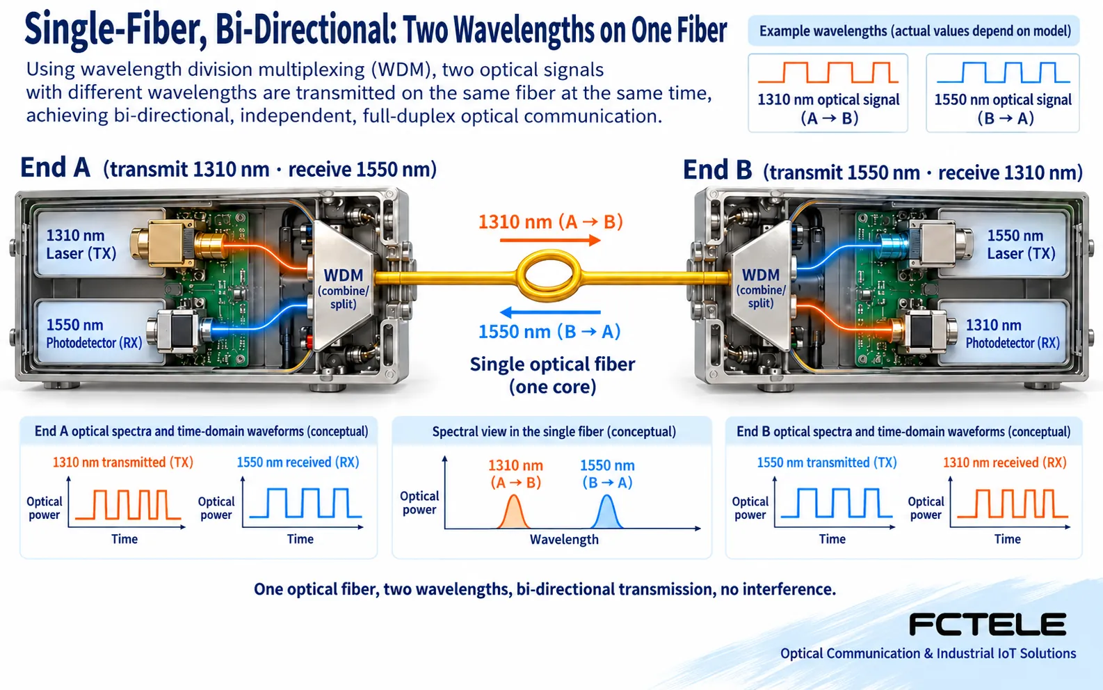
Wavelength division multiplexing lets different wavelengths share one fiber, then separates them with wavelength-selective components. The laser at end A sends the first wavelength into the shared fiber, and the matching receiver at end B detects it. End B sends a second wavelength back, which end A receives. Both ends need transmit and receive circuits; connecting two units that both perform only the same transmitting function will not create the required link.
For example, one end may transmit at 1310 nm and receive at 1550 nm, while the other transmits at 1550 nm and receives at 1310 nm. This is only a pairing example; actual equipment may use other combinations. Transmission must complement reception at the opposite end, while also meeting speed, optical power, service format, and manufacturer pairing requirements. Treating both units being single-fiber as proof of compatibility overlooks essential conditions.
3. Connecting the Outbound and Return Paths with Two Fibers
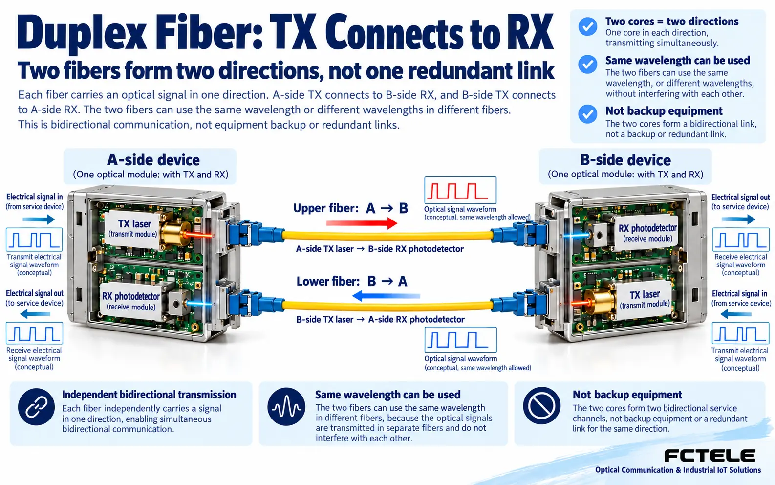
In a common dual-fiber arrangement, the TX transmitter at end A connects to the RX receiver at end B. A second fiber connects B TX back to A RX. These create the two directions. TX-to-TX and RX-to-RX connections do not provide the required link. Trace labels and ports through each patch-panel section instead of guessing transmit and receive roles from jacket colors.
Two fibers do not constitute two complete redundant links. Breaking one fiber normally affects one direction and may cause the protocol to declare the entire link unavailable. Backup protection requires a separately designed complete alternate path, equipment ports, and a switchover mechanism appropriate to the failure being covered. Two cords alone do not justify claiming that communication continues normally after either one is broken.
4. Connectors and Wavelengths Are Different Things
SC, FC, and LC primarily describe connector types. Do not identify equipment by assuming that SC means single-fiber or FC means dual-fiber. A suitable patch cord between different connector types changes only the physical connection. It does not convert single-mode into multimode or a dedicated video protocol into Ethernet. Check the end-face polish type as well; connectors that fit mechanically must not be mixed indiscriminately when their end faces differ.
Nor should dual-fiber devices be assumed to interoperate merely because their wavelengths match. Optical standards, receiver ranges, optical line rates, line coding, and manufacturer implementations may differ. Dedicated optical transmission equipment and Ethernet SFPs are especially unsuitable for indiscriminate substitution. Matching wavelength is one condition, not a complete compatibility verdict.
5. Comparing Options When Fibers Are Scarce
Suppose only one usable fiber remains between the field and the center, but bidirectional service is required. A matched single-fiber bidirectional pair can be evaluated. If two fibers are already available and the maintenance inventory primarily uses dual-fiber equipment, a dual-fiber solution may fit the existing system more easily. This choice matches resources and maintenance practices rather than ranking technologies. Include opposite-end changes, spare modules, test adapters, and maintenance costs in the comparison.
Wavelength-selective components can introduce loss, but engineering stability depends on the complete power budget, component quality, and site conditions. This does not establish that all single-fiber equipment is unstable. Transmit power, receiver sensitivity, and path loss can differ by direction, so calculate and measure them separately. Set test instruments to the correct wavelength and compare results with the corresponding receiver range. Testing one end does not establish that the other end passes.
6. Service Acceptance Matters More Than a Link LED
Identify the pairing role of each end when managing spares instead of recording only the series name. After replacing either end, check transmit and receive wavelengths and optical budgets again, ensuring that two versions with identical transmit and receive roles have not been paired incorrectly. Where optical modules are replaceable, follow the host compatibility list. Physical insertion alone does not demonstrate electrical-interface or firmware compatibility.
After installation, first check power and equipment identities, confirm the A/B or U/D pair, then test services in both directions. For Ethernet, examine actual throughput, frame loss, and errors. For serial services, check commands and replies; for telephone services, ringing, conversation, and release; for video equipment, each channel and its control return path. Acceptance criteria differ by service, and network ping cannot replace tests of every dedicated interface.
Keep records of optical-interface versions, wavelengths, fiber numbers, received power, software configuration, and test duration. When a fault occurs, check recent changes first rather than replacing several components simultaneously. End-face inspection and optical power measurement answer different questions; inspect again after cleaning. Never look into an optical port, and schedule a maintenance window before disconnecting fibers for testing.
References Cisco information on single-fiber BiDi pairing Use this to understand complementary transmission and reception; it does not prove that a particular Feichang model supports the same parameters. Feichang Technology integrated video optical transmission equipment provides an example of service-specific options; verify actual optical interfaces and opposite-end equipment against the ordered version.
Illustration note: The figures explain general mechanisms and are not photographs, measurements, or certifications of a specific product. Actual engineering must follow the specifications of the selected model.
Translated from the Chinese technical article. Source first published: 2021-07-22. Source last revised: 2026-10-13T17:09:56+08:00. Read the Chinese source
