


A fiber media converter fault cannot be diagnosed from one LED, and restarting is not the answer to every problem. Collect evidence layer by layer through power, copper ports, optical ports, frame forwarding, and higher-level applications. This article separates common symptoms into ten types, explaining causes, safe controlled comparisons, and results that still do not prove healthy equipment.
Preserve the State Before Diagnosing Power Problems
The first type is a completely dark unit; the second is restarting or disconnecting after a period of operation. First photograph LEDs, models, and power labels at both ends, and record timing and load instead of immediately disconnecting power. A correct supply rating does not establish stable voltage at the operating device terminals. Cable voltage drop, loose connectors, and load changes on a shared supply can all affect equipment. Compare with a known-good, compliant supply of the correct specification, and have suitably qualified personnel check terminal voltage. Do not open a live supply or mix adapters of different voltages. If replacement restores operation, continue investigating the original supply path rather than immediately declaring the converter board defective.
Type 3: No Copper-Port Link
The copper port is the Ethernet interface connected to the network cable. An unlit Link LED may result from cable faults, connectors, a disabled port, or incompatible speed settings. Connect a known-good short cable to known-good equipment and observe speed and duplex negotiation. Duplex describes whether transmission and reception can occur together; a full/half-duplex mismatch can cause errors or poor throughput. The need for a crossover cable depends on automatic crossover support, so a fixed rule that computers always require crossover cables is inappropriate. Change one variable at a time and record working and failing combinations, instead of replacing three cables and relying on memory.
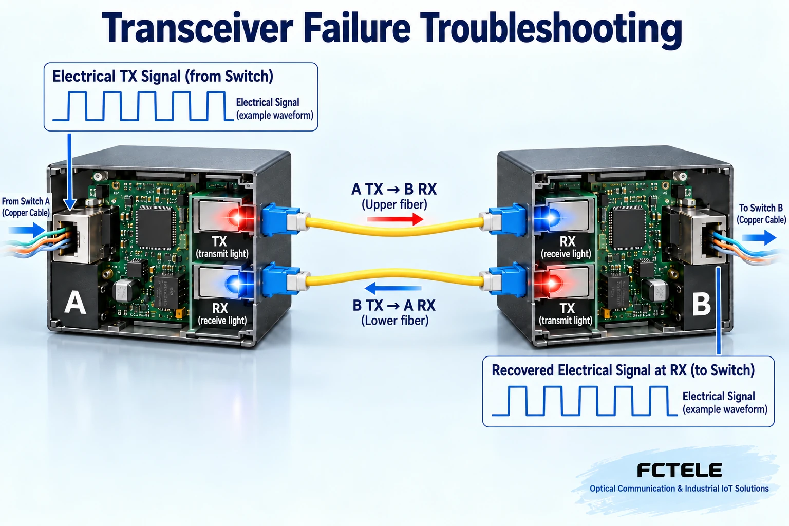
Types 4 and 5: No Optical Link or Only One Working Direction
Dual-fiber equipment uses separate fibers for transmission and reception, with local TX connected to remote RX. TX-to-TX connects two light sources without feeding the required receiver. Single-fiber bidirectional equipment shares one fiber using different wavelengths, requiring complementary ends. Also check speed, single-mode or multimode fiber, interfaces, and equipment compatibility. Swapping patch cords cannot fix wavelength or coding mismatches. Where two independent directions exist, one working direction proves nothing about the other. Check transmission and reception at both ends. Never look into an optical port; a visible-light continuity tool does not establish acceptable performance at the service wavelength.
Type 6: Optical Link Established but Frames Are Lost
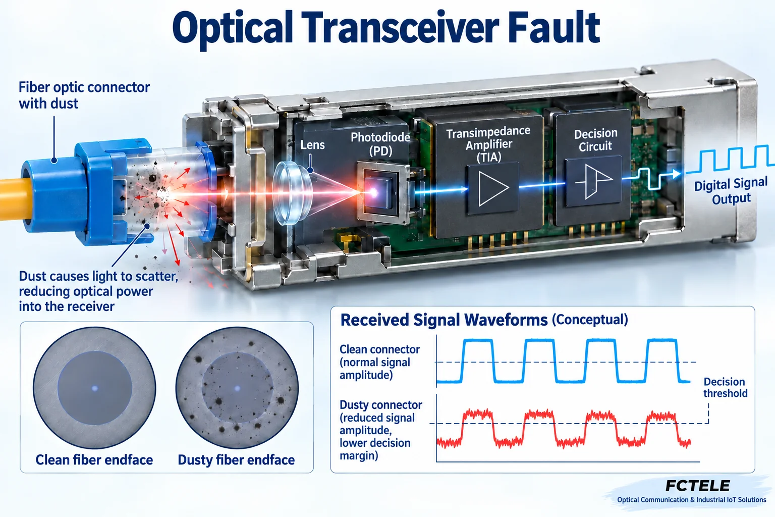
Enough light to establish a link does not mean that every symbol can be distinguished reliably. Connector contamination, bending, insufficient loss margin, or receiver overload can degrade waveform quality. Received power must fall within the module’s permitted window; stronger is not always better. If diagnostics are available, record optical power, temperature, and alarms at both ends. Otherwise, qualified personnel can measure with an optical power meter set to the correct wavelength. Compare against the manual, then inspect cleanliness and connections. Do not blindly replace a module with a longer-range one when frames are lost: its transmit power and receive range may be unsuitable for a short circuit. The illustrated waveforms explain decisions, not site measurements.
Types 7 and 8: Large-Frame Failures and Unavailable Services
Small frames working while large frames fail can involve maximum frame length, encapsulation overhead, or link errors. An Ethernet frame is a transmission unit. After VLAN tags or other encapsulation are added, equipment must accept the resulting length; IP maximum transmission unit is not synonymous with every frame-length specification. Test several lengths and loads and record error counters rather than hiding the cause by trimming application data. If LEDs are active but a service fails, check VLANs, addressing, gateways, firewalls, and application ports. A converter changes the medium; it does not automatically configure the application’s network. Successful ping proves only that one probe received a reply, not complete video, file-transfer, or industrial-protocol acceptance.
Types 9 and 10: Temperature-Related Faults and Linked Alarms
If rising temperature accompanies a fault, inspect installation temperature, cooling clearance, supply conditions, and component diagnostics. No single temperature limit applies to every device, and cabinet interiors may be considerably hotter than outdoor air. Some equipment offers link fault pass-through, deliberately dropping the copper link after an optical failure so a connected switch detects the remote problem. An extinguished copper LED may therefore not indicate damaged copper cabling. Support, enablement, and alarm direction depend on model and configuration. Simultaneous faults on chassis cards also require common-supply and backplane checks instead of treating each card as an independent failure. Confirm explicit equipment permission and procedures before powered insertion or removal.
Establish a Reproducible Short-Link Baseline
Suppose an interbuilding circuit works intermittently. During a maintenance window, first test compatible equipment at both ends with a known-good short patch cord. A healthy short link and faulty long link shift attention toward site fiber, connectors, and power margin, but do not prove the absence of thermal or load-related equipment problems. Restore the original circuit, keep service conditions comparable, and replace sections individually while recording results. If replacing the equipment pair restores operation, continue separating supply, module, and main-unit variables. Replacing everything proves only that the new combination works. The purpose of testing is to narrow possibilities, not convict one component after a single recovery.
What to Accept After Repair
Repeat the scenario that triggered the original fault. Check both directions, sustained service, different packet lengths, expected peak loads, and whether error counters continue increasing. Save before-and-after power, speed, configuration, timing, and equipment identifiers for future recurrence. Restarting can be a maintenance action, but preserve evidence first. Recovery after restart means only that the symptom has temporarily disappeared. Explicitly mark unexplained random problems as requiring verification rather than claiming a permanent fix. Separating power, media, forwarding, and applications makes replacement decisions evidence-based and maintenance risk more manageable.
Mechanism reference:Official reference 1. General mechanisms and examples do not replace the corresponding model manual.
Diagnostic Limits to Preserve When Consolidating Older Questions
Handling of damaged frames depends on the hardware architecture. Do not broadly claim that bad frames remain forever in a buffer and freeze the unit. Buffers are finite: examine port errors, congestion, and drop counters alongside service load and logs. Where an unmanaged unit lacks counters, collect them from an adjacent switch and compare with verified matched equipment. Without evidence, do not attribute every intermittent issue to a failed chip.
Fiber end faces cannot be inspected with the naked eye, and one RX-power reading is not a normal standard for the entire industry. Use suitable instruments, identify the measurement point and wavelength, and interpret results against that receiver’s window. Feichang basic and managed products differ in status-collection capabilities. Check both service compatibility and maintenance features when buying replacements; similar product names do not guarantee the same management protocol or remote-fault linkage.
Product information:Feichang B-series Gigabit Fiber Media Converter;Feichang Managed Fiber Media Converters. Management, supply, and optical options are not interchangeable across products; confirm the ordered model. Images are generic mechanism illustrations with simulated waveforms, not measurements or cutaways of a particular product.
Translated from the Chinese technical article. Source first published: 2019-08-29. Source last revised: 2026-10-13T17:09:56+08:00. Read the Chinese source
