


Gigabit converter copper ports can still be limited by cabling. LEDs or one transferred file do not certify installed cable to its agreed category. Define the boundary, instruments, adapters and limits before interpreting crosstalk, attenuation and reflections. Copper certification, optical measurements and complete-converter tests complement rather than replace one another.
1. Fiber extension cannot repair Ethernet copper
Copper signals must pass twisted pairs, connectors and PHY circuitry before later processing. Balanced pairs carry differential signals, and twisting reduces interference. Untwisted pairs, poor terminations and mismatched connectors alter transmission. Better optics cannot eliminate those defects.
Common Gigabit copper Ethernet requires all four pairs rather than older partial-pair arrangements. Eight connected conductors are insufficient unless pair assignment and high-frequency performance are correct. A continuity tester finds opens/shorts but cannot complete category certification. Negotiating Gigabit is an operating state, not a cabling certificate.
2. Permanent links and channels answer different questions
A permanent link evaluates fixed installation such as panel-to-outlet cable and associated connections. A channel also includes equipment/user cords. Bad jumpers can therefore spoil a channel after fixed cabling passes. Reports using different models cannot be compared solely by cable ID and values to accuse the instrument of error.
Use adapters matching the test model. Permanent-link testing is not attaching arbitrary ordinary cords and subtracting a guessed length. Adapters and calibration account for test connections. Record main/remote units, adapters, limits and calibration. A green pass with the wrong boundary may answer the wrong question.
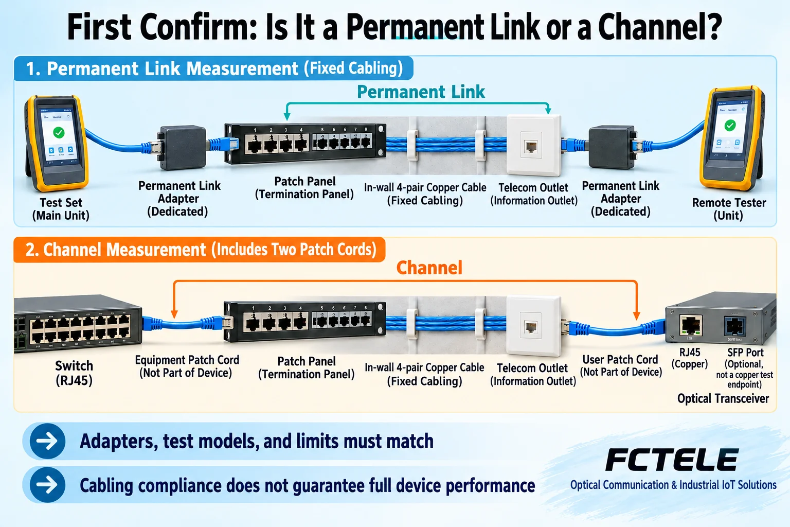
Older standards explain history but do not automatically govern new work. Use the contract, applicable standards version, category and instrument-supported limits. Do not copy one Internet table as every cable threshold. Limits vary with frequency, category and model; one passing frequency cannot pass the whole band.
3. Insertion loss: attenuation through the link
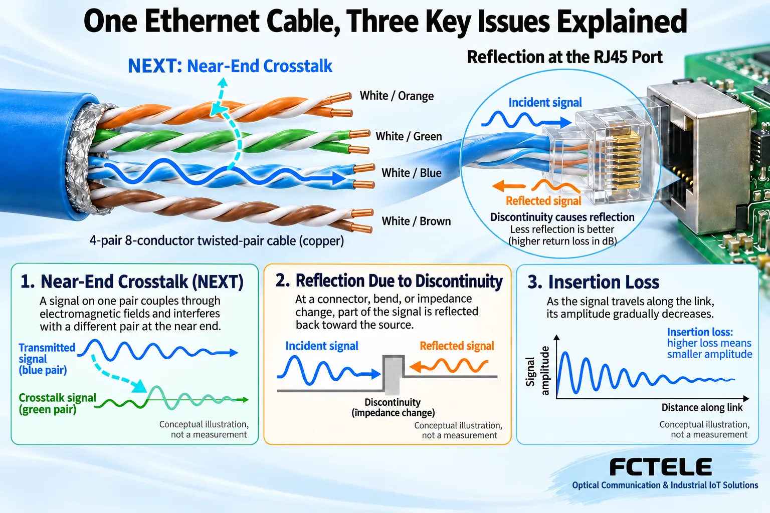
Insertion loss describes signal attenuation across the tested link. Length, conductors/materials, frequency and connections affect it; being within a length limit is insufficient. Check selected limits across the full band and instrument units/definitions. Optical dBm readings do not belong in copper insertion-loss fields.
For abnormal loss, compare cable/connector category, actual route/length and whether cords are included, then inspect damage or moisture clues. Recovery after replacing a short jumper identifies a variable, not certification of in-wall cable. Retest the original model and retain before/after reports.
4. Crosstalk: signals coupled from neighboring pairs
Changing signals on one pair electromagnetically couple into another. NEXT, near-end crosstalk, concerns the transmitting-end side; far-end crosstalk concerns the opposite side. Near/far follow test direction, not fixed panel/converter locations. Certification may test pair combinations from both ends; one single-end reading is insufficient.
Excess untwist, split pairs and incorrect assignments harm balance. Follow connector procedures to preserve pair structure rather than repeatedly trimming by trial and error. Reports may include power-sum and attenuation-related comparisons for simultaneous pairs. Interpret these with instrument guidance and selected limits, not as complete actual application signal-to-noise measurements.
5. Return loss: more reflection is not better
Impedance discontinuities reflect some signal and can disturb reception. Return loss compares incident and reflected power. Under the usual positive definition, higher return loss under equal conditions means less reflection. Do not assume lower is better because it is called loss. It relates to attenuation but is not another name for insertion loss.
Compression, sharp bends, unsuitable connectors and installation damage are clues. Instrument distance-to-fault functions narrow a search but cannot by themselves identify a damaged component. Check cable type/propagation settings and actual structure. Repeat complete testing after repair, not only the failed parameter.
6. Apply reports to converter projects
If a permanent link passes but converter copper repeatedly falls back, first inspect added channel cords, copper settings, connectors and port status, then optics separately. A converter fault label cannot justify skipping copper, while a passing copper report cannot end checks of power and optical matching.
The FCTEL managed single-optical/single-copper Gigabit series describes copper adaptation and local/remote management. Suitable models expose current state for comparison with cable reports and frame tests; autonegotiation cannot replace certification. Categories include different interfaces, management and power. Accept the exact order rather than every converter against one series feature set.
Retain cable ID, endpoint locations, category, model, standards version, instrument/adapter identity, calibration, complete results and repair history. A screenshot alone may not identify the segment or limits. Full reports let another engineer repeat the same boundary rather than simply documenting a lit link.
Reference note: measurement boundaries refer to Fluke Networks permanent-link guidance; loss/crosstalk concepts refer to return-loss documentation and near-/far-end crosstalk documentation. Product references:FCTEL product categories and series details. Figures are not measurements or specific product photographs. Formal acceptance follows applicable project standards and complete reports.
Translated from the Chinese technical article. Source first published: 2019-08-29. Source last revised: 2026-10-13T15:39:27+08:00. Read the Chinese source
