


When several fiber services in one chassis fail simultaneously, do not immediately condemn every converter card. When only one slot has a problem, do not automatically replace the entire power system either. A chassis consolidates interface cards, reducing separate adapters and untidy wiring, but introduces shared influences such as power distribution, cooling, and connectors. First establish the extent of the fault, then distinguish common components from individual cards. This discussion concerns chassis for Ethernet fiber media converter cards; telephone, video, and other service cards require interface acceptance tests specified in their own manuals.
1. A Chassis Does More Than Place Equipment Together
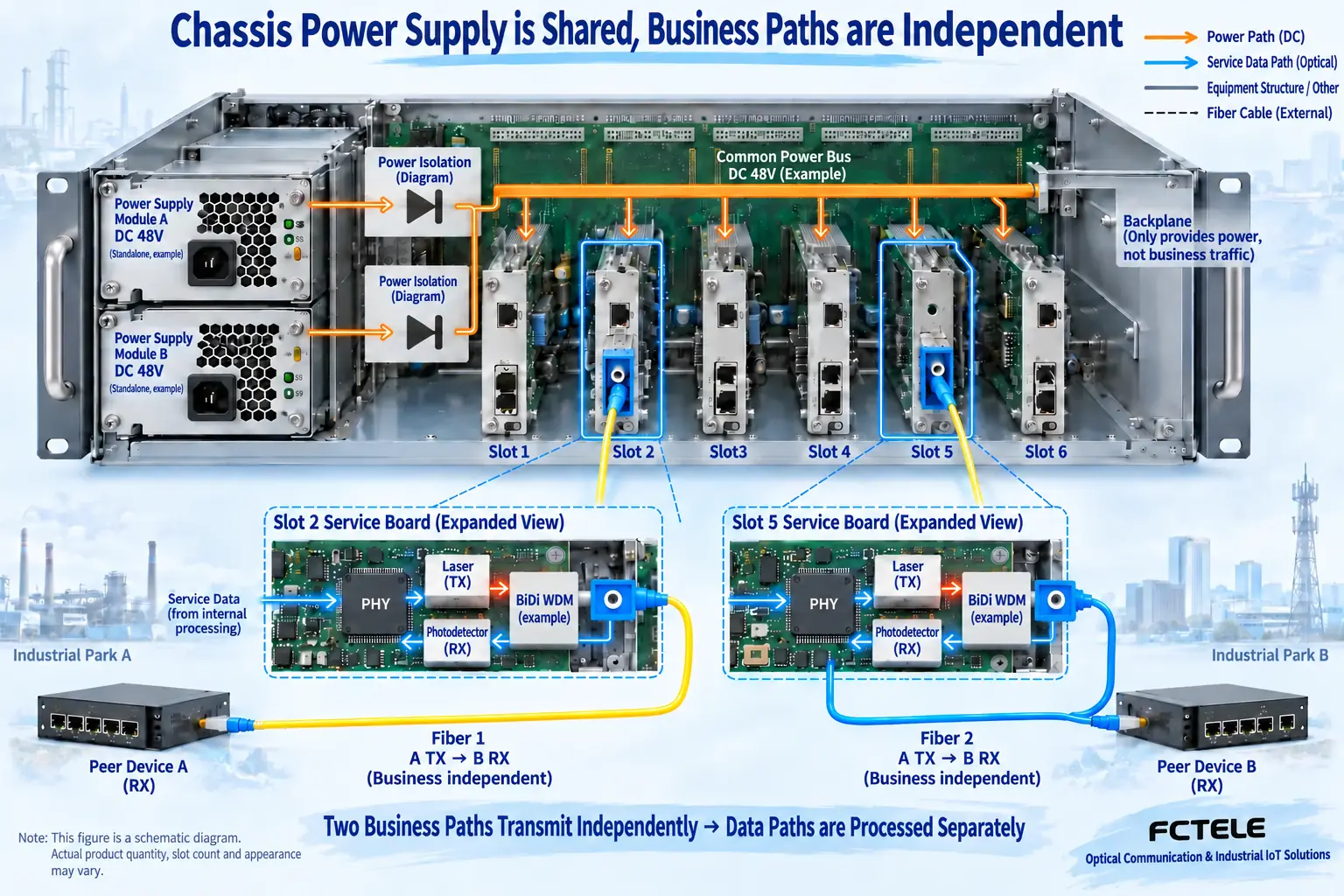
A shelf for complete standalone units can resemble a card chassis, but the internal relationships differ. A shelf primarily holds independent boxed devices; whether they share power depends on its construction. A card chassis supplies compatible service cards through slot connectors and shared distribution. Its backplane is the circuit board connecting slots inside the chassis. Having a backplane does not mean that all service data automatically converges onto one uplink. Some chassis distribute only power and management signals, while each card retains its own copper and optical ports. Such a chassis cannot be treated as a multiport switch.
On an Ethernet converter card, a physical-layer circuit receives electrical signals from the network cable, and an optical transmitter sends the information into the fiber. Incoming light in the reverse direction is converted back to electrical signals and delivered to the copper port. The chassis supplies the required operating conditions; it cannot correct an incorrect optical rate, wavelength, or connection. Data paths are independent, but power paths may be shared. This is why simultaneous failures across several cards and a single-card failure require different inspection sequences.
2. Record Which Slot Serves Each Circuit
Before maintenance, photograph the front panel and cable labels. Record the chassis, power-supply and card models and hardware versions, along with slot numbers, fiber destinations, opposite-end equipment, service names, and current alarms. The number of slots is not necessarily the number available for service cards: a management card may occupy one, and cards of different widths or series may have compatibility restrictions. Fitting physically does not establish matching electrical definitions, power, or management protocols. Use replacements from a manufacturer-confirmed compatibility list, and never force in a card from another series.
Also record when the problem appeared: after adding a card, after a site power outage, or as cabinet temperature rose? If a slot became abnormal after a cable change, investigate that cable and interface first. If several slots alarmed in the same second, check input power, shared supply alarms, and cooling first. Timing and fault scope are more useful evidence than LEDs looking similar. If the maintenance management channel is inaccessible, test services separately rather than treating a management-card fault as a complete service outage.
3. Why Dual Power Supplies Do Not Eliminate All Outages
Redundant power supplies generally mean that the design permits one unit to carry the load if the other fails. This requires sufficient capacity in the remaining unit, support for that operating mode, and correct connections. If both supplies connect to the same power strip or upstream breaker, loss of that shared source still removes both feeds. Power-unit redundancy and independent upstream supply paths operate at different levels. Counting plugs does not prove that common failures have been eliminated.
Before adding cards, check total load and cooling requirements against the chassis configuration limits. An unloaded output measurement alone does not establish a healthy supply: poor contacts, cable loss, or insufficient supply capacity may appear only under load. Non-specialists should begin with safely accessible alarms, input connections, and external supply status. Qualified personnel must perform electrical measurements under authorized conditions. Never open a live power-supply enclosure, insert metal tools into backplane connectors, or bypass protection to keep services running.
4. Narrow the Scope from the Whole Chassis to Slots and Cards
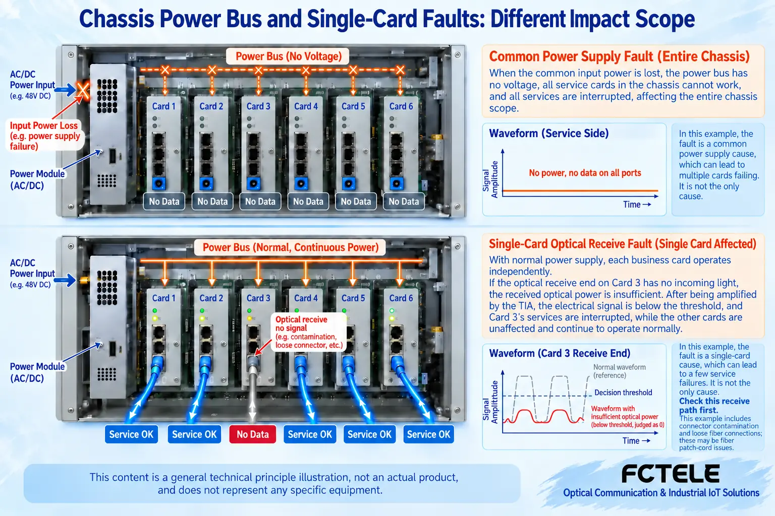
For a whole-chassis problem, compare the two input feeds and supply-unit states first, then inspect fans, temperature, and common alarms. If power LEDs remain on but every card repeatedly restarts, preserve alarm and service-outage times and investigate instability under load rather than repeatedly resetting all cards. If only some slots are affected, establish whether they share a distribution section or connector structure. Confirm that relationship from the manufacturer’s drawings instead of inferring it from neighboring positions.
For a single-card problem, first inspect copper-port negotiation, optical pairing, connector cleanliness, and the opposite end. Compare against a verified compatible replacement, changing only one variable at a time. If a replacement card also fails in the same slot, while the original card works in another authorized slot, the slot or shared connection deserves closer investigation. If the fault moves with the card, investigate the card itself. Moving slots changes circuit and service arrangements: obtain a maintenance window, save configuration, and mark original positions rather than swapping cards casually in a running production network.
5. Hot Swapping Requires Permission for the Actual Model
Card-based describes a mounting format; hot-swappable describes permission to replace equipment while powered. They are different properties. Even where a chassis supports hot swapping, confirm that the particular card, supply unit, and procedure are covered. Follow the manual for antistatic protection, screws, and extraction handles, avoiding angled insertion or force. Equipment with no stated hot-swap support requires the appropriate safe shutdown procedure; experience with another chassis is not permission to experiment.
Feichang Technology FCK12-a2/d2 2U integrated access chassis product information describes compatibility with designated company interface cards, dual supplies, and management options. These features help centralized maintenance, but usable slots, card types, supply combinations, and hot-swap procedures must be checked against the ordered configuration. Interpret differing slot descriptions on the page in light of management-card occupancy, rather than extending one page’s features to every chassis.
6. Verify Services After Recovery, Not Just Cleared Alarms
After recovery, check copper and optical port states slot by slot, test services in both directions, and observe whether realistic loads cause restarts, frame loss, or repeated alarms. Record duration, data volume, and changes in error counters instead of saving only one successful ping. Where an approved test includes supply redundancy, the responsible power and network personnel should follow the plan; do not unplug an unidentified supply just to see what happens. Finally restore labels, covers, and configuration backups, and record replacement part identifiers and symptoms for future comparison.
Source note: Based on the corresponding Feichang chassis product page, with general chassis mechanisms distinguished from actual configurations. Images are generic cutaway illustrations, not product photographs or site measurements, and do not represent every slot connection or power implementation. Current model manuals and manufacturer confirmation govern compatibility, electrical safety, and replacement procedures.
Translated from the Chinese technical article. Source first published: 2020-07-13. Source last revised: 2026-10-13T17:09:56+08:00. Read the Chinese source
