


When a fiber media converter fails to communicate, separate power, copper-port, optical-path and service-configuration checks, then establish a baseline using a known-good short link. One illuminated LED cannot prove the whole link works. Do not replace everything at once. The two directions can behave differently, so verify optical power and data transfer separately in each direction.
Record the installation before disconnecting cables
Photograph both nameplates, optical and copper ports, indicators and power connections. Record when the fault began, recent changes and the affected scope. Check power specifications, port enablement, module seating and unusual heat. Interpret LEDs using the model manual: an indicator may show power, link or activity, and green does not always mean the application works. Swapping patch cords before recording the wiring can turn the original fault into a new connection error.
A working copper link does not prove reachability beyond the fiber
Check cable quality, negotiated speed and duplex settings. Use known-good equipment and a short Ethernet cable to exclude a local connection fault. Examine interface errors, packet loss and link drops rather than one ping. If the link establishes but performs poorly, check duplex mismatch, congestion and uplink capacity. VLAN, IP-address and gateway errors are network configuration issues that a media converter generally cannot repair automatically.
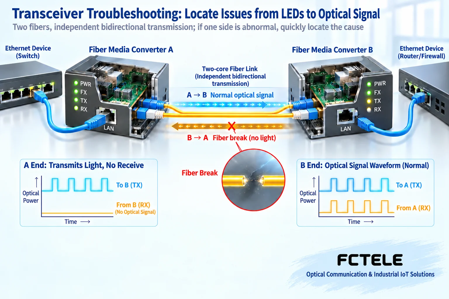
Match optical specifications and transmission directions
Match single-mode or multimode fiber, speed, wavelength, connector and end-face type. With duplex fiber, connect local TX to remote RX. With single-fiber bidirectional equipment, pair complementary TX/RX wavelengths rather than relying on A/B labels. Transmit and receive capabilities may differ between directions. Check each separately when only one fails; this does not mean end B can only receive. A compatible short-fiber test can separate equipment/configuration problems from the installed optical path, but check receiver overload before directly connecting high-power modules.
Optical power is evidence, not a complete diagnosis
Use a power meter suitable for the wavelength. Identify the measurement point, record the reading and compare it with the relevant receiver operating range. Low power can result from dirty connectors, bends, splices or component losses; excessive power can also exceed the receiver range. There is no universal pass value for every converter. If power is acceptable but communication fails, check interface type, configuration and data errors. A power meter cannot prove that every packet is correct.
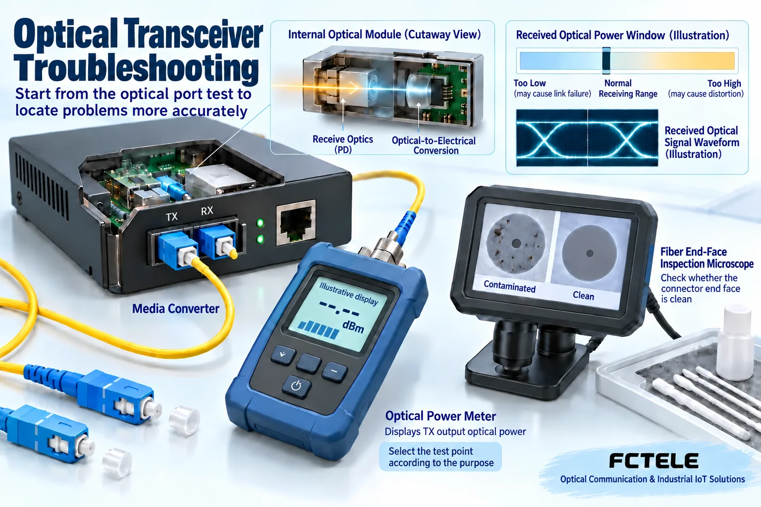
Change one condition at a time, then test recovery
First substitute a confirmed-compatible patch cord; replace equipment or modules as necessary afterward. Record each result. If a short link works but the installed link fails, investigate the line and environment first. If both fail, return to model and configuration checks. After restoration, test sustained bidirectional traffic, power cycling and unplug/replug recovery. Save normal LED states and power readings as a baseline. Follow procedures for connector cleaning, electrostatic protection and power safety.
Example: the short fiber works, but the installed line loses packets
Keep the equipment and configuration from the working short-link baseline and change only to the installed optical path. Record whether both directions are affected. Check patch cords, distribution panels, connector cleanliness and optical power. Changing equipment and modules simultaneously removes the basis for isolation. If optical readings are normal, examine copper-port errors, speed, network load and power fluctuations. Test individual sections when necessary. Occasional file transfers or successful pings do not exclude persistent errors. Compare error-counter changes over time and actual service behavior instead of declaring hardware faulty from one file-transfer duration.
Make local-versus-remote comparisons repeatable
Use the same two devices for local and remote tests, with clear direction labels. Establish a baseline with a confirmed-compatible short link before inserting the field fiber. Even the short link must avoid receive overload; do not connect long-reach modules with a very short jumper without checking specifications. Passing locally and failing remotely identifies a difference worth investigating along the installed path, but compare field power, the remote copper connection and configuration as well. It does not automatically prove the fiber is broken.
Specify the measurement point. Connecting a power meter directly to TX measures transmitter output power. Connecting the fiber arriving from TX to the meter immediately before remote RX measures incident power at that receiving location. These readings support different judgments. Meter wavelength settings, adapters and connection losses also affect results. Record each direction independently. One number cannot prove bidirectional operation, and a meter value in an illustration is not the permitted range for that model.
If the fault follows a particular jumper, investigate its end faces, connectors and bends. If the same line is stable with verified compatible equipment, investigate the original device and power supply. Before substitution, confirm interface speed, fiber type and wavelength pairing, and preserve configuration so that the replacement does not introduce incompatibility. Disconnecting a production link interrupts service, so use a maintenance window. Suspected shared-power or chassis-slot problems should not be diagnosed by repeatedly pulling cards.
Compare bidirectional data volumes, error counts and application response too. If requests succeed but large packets or high load are unstable, continue checking link errors, queue congestion and host performance. A slow file transfer alone does not prove the converter is faulty. Suitable FCTEL managed products can help read status, but the available local and remote items depend on the model. Record both baseline and failure conditions to support future comparisons.
For example, forward video may work while control commands fail intermittently. Seeing a picture does not prove both fibers work. First confirm that control traffic actually uses the same link, then compare the return optical port and host response. If return incident power is within the manual range and corresponding link errors do not rise, investigate the control service and access policies. If return errors change with a particular fiber or connector, preserve the comparison and investigate that direction. Swapping both fibers while changing application settings destroys the connection between direction labels and evidence.
Product references:FCTEL B-series Gigabit fiber media converters;FCTEL managed fiber media converters. Management, power and optical options are not interchangeable across products; confirm the ordered model. Figures show generic mechanisms; simulated waveforms are not measurements or product cutaways.
Translated from the Chinese technical article. Source first published: 2019-08-08. Source last revised: 2026-10-13T17:09:56+08:00. Read the Chinese source
