


Fiber media converters from different brands may interoperate when the necessary conditions match, but identical-looking optical ports or Gigabit labels do not guarantee it. Check Ethernet interfaces, optical transmission type, transmit/receive configuration, power windows and actual traffic. Management and alarms may depend on particular implementations, so a working data link does not mean every remote-management function is compatible.
First establish that both are matching Ethernet products
A media converter usually converts media for a corresponding Ethernet service. Video, serial and E1 optical terminals also have optical ports but follow different service rules. Matching wavelengths alone cannot make arbitrary optical devices interoperate. Model documentation must specify copper and optical port speeds and types. Some products incorporate switching, while others operate closer to physical media conversion. Establish their actual behavior. A brand name cannot replace a complete interface definition, and similar enclosures do not prove identical chips or formats.
Check optical-port speed, not just copper-port speed
Multispeed copper negotiation does not guarantee that the optical port supports the same combinations. Fast Ethernet and Gigabit optical links have different requirements and may not automatically fall back to a common rate. Check the specific Ethernet optical interface and permitted modes. One Gigabit copper port is not a statement of the complete link capability. Light-load communication also does not prove the target load is supported. Record supported speed, actual negotiation and module for each port instead of retaining just a number from the product title.
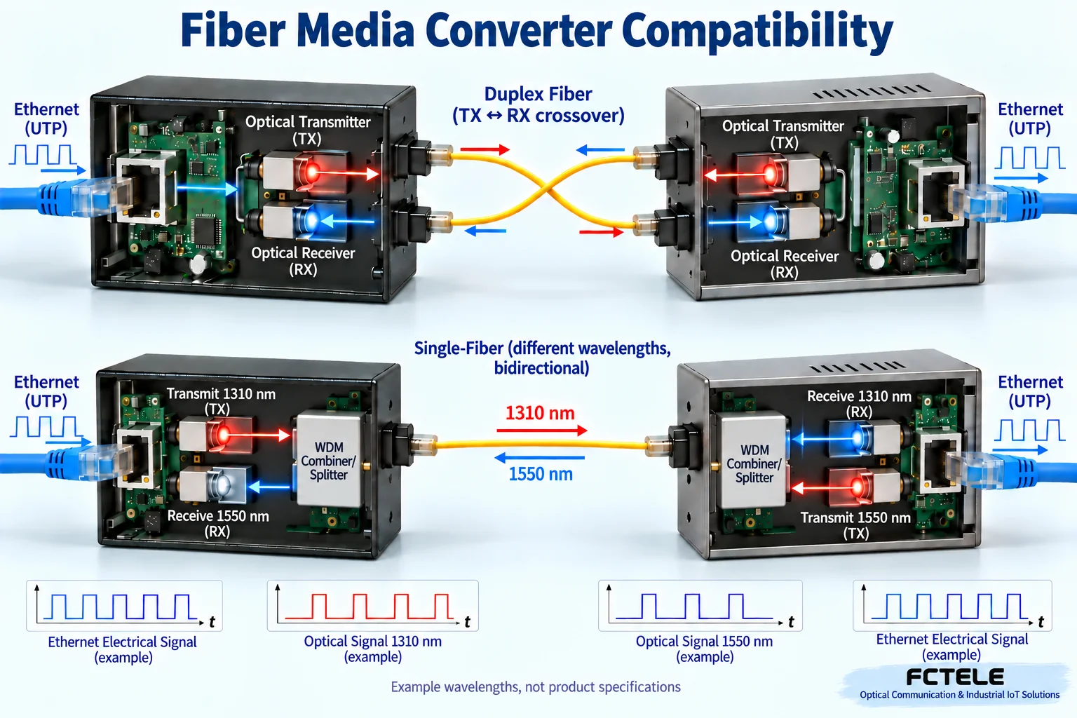
Why duplex fiber crosses transmit and receive
In a typical duplex-fiber connection, transmission from one end must reach reception at the other; a second fiber carries the reverse direction. TX-to-TX and RX-to-RX do not form the required link. Connectors and wavelengths must also match the fiber type and standard. Arrows indicate signal relationships, not universal port positions. Confirm installation labels and test even neatly arranged cabling. The two directions can fail separately, so one normal LED cannot prove the reverse direction is reliable.
Why single-fiber bidirectional links need complementary configurations
A suitable bidirectional design shares one fiber between two directions, commonly separating them by wavelength. Each transmitter must match the receiving requirements of the other end; two arbitrary identical modules are not sufficient. Example wavelengths explain the relationship rather than specifying every product. Check rate, distance conditions, fiber type and standard too. Single fiber does not mean one-way transmission, and two fibers are not inherently faster. Fiber count, direction and service capacity are separate questions.
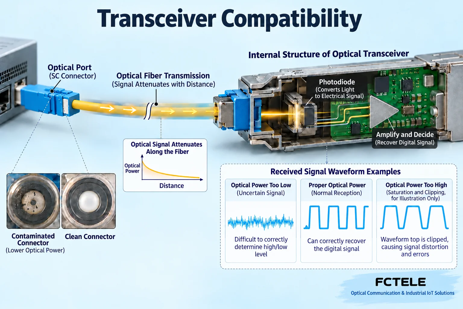
Why more optical power is not always better
A receiver has an operating power range. Weak light can be difficult to distinguish, while excessive light can also cause abnormal behavior. Arriving power depends on transmission, line losses, connectors and other conditions, so a distance label cannot replace a power budget. Use suitable power meters and inspection tools in both directions rather than inventing one threshold for every module. Dirty end faces can scatter or reflect light; follow cleaning procedures and never look into a light source. Determine adjustments or attenuation from specifications and measurements rather than increasing transmit power by trial and error.
Why data compatibility and management compatibility differ
Exchanging data under matching Ethernet rules does not prove compatibility of proprietary remote management, chassis communication or alarms. Some OAM and status-detection functions also require support, configuration and implementation conditions at the other end. Verify model-specific LFP behavior through documentation and tests. One LED cannot indicate that every remote service is healthy. Define the management boundary and confirm requirements with manufacturers when mixing brands. Data interoperability and a unified monitoring system are different product requirements.
Put FCTEL model features at the correct level
The FCTEL B-series Gigabit converter page describes relevant IEEE Ethernet support and single-/dual-fiber options. The managed Gigabit converter page lists maintenance features such as OAM and LFP. These can support suitable designs, but confirm management combinations and power versions. Chassis or internal-power features cannot be extended to every external-power product. For mixed-brand designs, check the data link and required maintenance capabilities separately, giving each feature a defined purpose while retaining limits that a standard name alone cannot guarantee.
Establish a short-fiber baseline before field deployment
For a proposed mixed-brand link, check equipment and module documentation, then establish a link using suitable short fiber under permitted safe test conditions. Check short-link receive power for high-power long-reach modules and verify both traffic directions. Introduce the installed line and target traffic load next, recording throughput, errors and status. This is a hypothetical example, not a deployed customer case. Change only one endpoint or section at a time; changing cable, modules and power simultaneously obscures the cause. The tested scope must match the actual load.
Troubleshoot in layers when communication fails
Start with power at both ends and the actual optical interface type. Then check transmit/receive pairing, fiber type and power, followed by copper speed, cable, VLANs, addressing and applications. A normal link LED with a failed application can result from later network conditions; do not immediately blame brand incompatibility. A few successful pings do not prove long-term high-load stability either. Preserve alarms, errors and before/after replacement records, reproduce the failure conditions where possible, and do not describe temporary recovery after reboot as a permanent repair.
Define the verified compatibility scope at handover
Record complete endpoint models, modules, interface standards, fiber and wavelength, power measurements, copper speed, management settings and traffic tests. State that data interoperability was verified for that particular combination and conditions, and separately identify untested or unsupported management functions. Recheck after version changes or higher loads. Cross-brand compatibility follows physical, electrical and protocol conditions plus actual evidence. A defined compatibility scope supports maintenance better than promising that every brand can be mixed freely.
Use a two-end compatibility table
List copper speed, optical standard, fiber type, wavelength, connector, single-/dual-fiber arrangement, transmit power and receive window for each device. Duplex fiber crosses TX and RX; single fiber needs complementary transmit/receive configurations. Similar housings, Gigabit labels or equal distance ratings cannot replace this table. Check required traffic frames and management functions too. Basic communication does not justify promises of cross-brand remote OAM, alarm coordination or every extended feature. Conclusions must name the tested combination and conditions.
Higher receive power does not mean greater assurance
The receiver must identify signals within its permitted window. Too little light can be hard to resolve; too much can exceed the operating range. Testing on very short fiber does not necessarily represent the installed long-distance path. Conversely, long-reach transmitters on short fiber may need treatment specified by the manual. Use instruments suitable for the wavelength and connector, recording end-face and connection losses. An illuminated LED cannot replace a power-window check. Never look into an optical port or add unauthorized light sources or amplifiers.
Conclude separately on transparent transport and management pairing
Basic Ethernet media conversion, oversized-frame support, link-fault propagation and remote management are different functional levels. FCTEL B-series and managed converters offer different configurations; a management function may require a specified peer or chassis. Acceptance records can separately mark basic service passed, particular management functions verified and other functions untested. Recheck key conditions after module, firmware or equipment changes and retain the original combination data to identify what changed.
Retain a compatibility baseline when firmware changes
Source article 2937 also highlights firmware and software in multivendor environments. Turn this into a defined change procedure rather than assuming regular upgrades always improve compatibility. Establish which known problem a release fixes and whether it applies to the model and hardware revision. Back up supported configuration and arrange a maintenance window. Before upgrading, record both models, versions, copper negotiation, optical power and traffic results; repeat tests on the same line and load afterward. If maintenance functions need a specified peer, separately verify local management, remote status and fault coordination. Continued data forwarding does not verify every function. Prepare rollback only when supported by the manufacturer and authorized. Do not flash another brand of firmware indiscriminately.
Product and mechanism references:FCTEL product detail 616;FCTEL product detail 633. Generic mechanisms and hypothetical examples do not replace the manual for the actual model.
Illustration note: figures show generic mechanisms, not product cutaways or field measurements. Example wavelengths do not apply to every model. Actual interfaces, power windows and management pairing depend on current model documentation and testing.
Translated from the Chinese technical article. Source first published: 2019-07-22. Source last revised: 2026-10-13T17:09:56+08:00. Read the Chinese source
