


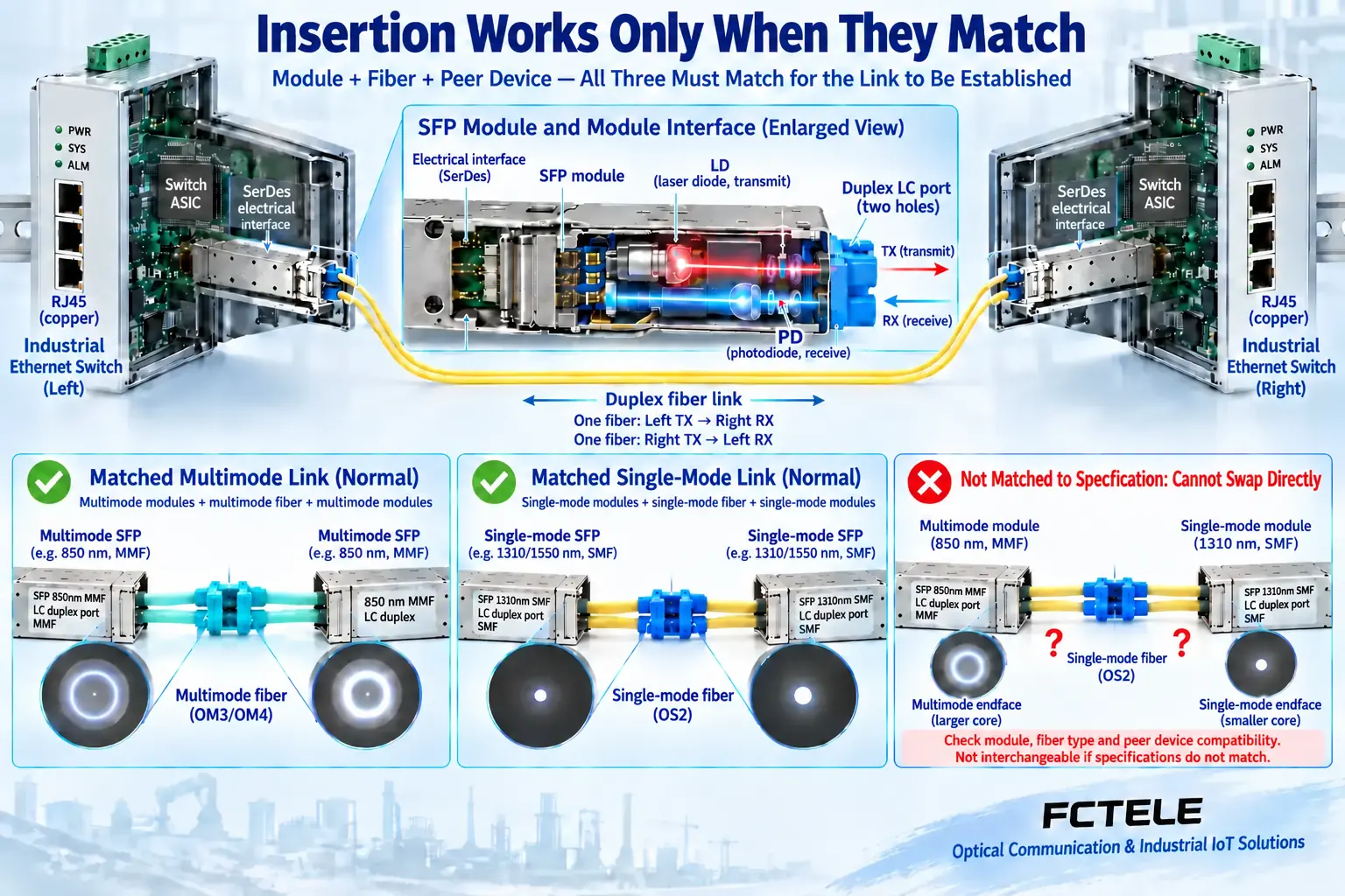
Matching port shapes do not make single-mode and multimode configurations freely interchangeable. A fixed optical port follows the ordered equipment specification. Even a pluggable SFP port must satisfy switch support, module specifications, installed fiber and remote reception requirements together. Without documented compatibility, changing a module or jumper does not complete a migration.
1. Identify the components that determine optical operation
An industrial switch forwards Ethernet data between ports. Its optical interface converts electrical signals to light and received light back to electrical signals. The switching chip processes frames, the module’s laser transmits, and its photodetector receives. Single-mode and multimode concern this optical path; they do not mean a switch supports one endpoint or multiple ports.
Fixed-port equipment has the relevant optical components installed internally, which users generally cannot reconfigure as easily as replacing a jumper. A pluggable port instead provides a module cage and electrical interface. SFP is a common pluggable form factor. Fitting the cage establishes mechanical correspondence only: the host must also support the speed, electrical interface and identification method. A module that fits need not carry traffic successfully.
An order specifying single-mode single-fiber, single-mode duplex-fiber or multimode duplex-fiber combines two conditions. Mode describes propagation; fiber count describes how many cores a bidirectional link occupies. These are independent. Single-mode does not mean one network node, and multimode does not mean many ports. Before replacing anything, separately record the existing interface, installed fiber and core count.
2. Why all fibers are not equivalent transparent channels
Fiber comprises a core and cladding that guide light. Under its specified operating conditions, single-mode fiber mainly carries one spatial mode, whereas multimode fiber permits multiple modes. Modes can arrive at different times and broaden a short pulse. Reception therefore requires both enough light and data distinguishable at the correct instant. Light being present cannot establish suitability on its own.
Single-mode avoids that particular intermodal delay difference, but still has other dispersion and loss limits. Multimode is not inherently poor quality; it works well within a suitable distance, speed and fiber grade. Actual limits follow the optical interface and components, rather than universal claims that single-mode always reaches tens of kilometers or multimode stops at two kilometers.
A module’s launch method, wavelength band and receiver design form a system with the fiber’s propagation properties. Identical connector shapes do not remove these differences. An adapter addresses part of the mechanical connection; it cannot turn multimode cable into single-mode cable or alter laser and receiver requirements.
3. When a replacement can be evaluated
Suppose a link originally uses multimode interfaces and cabling, and a project proposes modules intended for single-mode fiber. Host support is necessary, but so are an appropriate single-mode route, compatible remote modules and correct jumpers. Do not assume the old multimode cable remains suitable merely because both modules change. Conversely, when upgrading speed over retained multimode cabling, consult the combination of the new interface and that fiber grade; prior connectivity is insufficient.
Some particular interfaces support other fiber types under explicit conditions, sometimes requiring mode-conditioning patch cords or another special arrangement. That is an interface-specific exception, not proof that every single-mode module supports multimode fiber. Consult official documentation for the exact model and confirm field conditions. Obtain clear supplier support if documentation is ambiguous; an illuminated LED during a trial does not establish long-term compatibility.
Check both ends. Duplex fiber connects local TX to remote RX; single-fiber BiDi additionally requires complementary transmit and receive wavelengths. Compatible speed and interface rules, suitable connector end faces and adequate optical budget are prerequisites. Both ends being Gigabit or SFP does not remove the remaining checks. Module support also does not make every host speed possible.
4. Specify the complete FCTEL configuration
FCTEL’s DIN-rail industrial switch category includes different optical/copper combinations, with SFP interfaces on some products. For example, the domestically sourced lightly managed model with sixteen Gigabit copper and eight Gigabit SFP ports documents those port types. A project can select that structure for its port requirements. However, the page is not a compatibility list for every third-party module or fiber type.
Ask the supplier to confirm the full host model, supplied modules, transmit/receive wavelengths, fiber, connectors and allowable receive range. Series-level distances or typical media descriptions are not universal limits for a particular installed module. This discussion uses the documented optical-port structure to explain replacement assessment. It adds no unsupported temperature, certification, zero-delay or unrestricted hot-swap promises.
Fixed and pluggable optical ports also have different maintenance routes. A fixed-port endpoint lacking the required configuration may need replacement; a pluggable host can be evaluated for supported module changes. Whether live replacement is permitted, how a latch releases and whether a port must first be disabled are model-manual matters. Do not copy another brand’s installation rules.
5. Retain comparable evidence before and after migration
Save configuration and link records first, including negotiated state, both module models, normal traffic and error counts. Change equipment within a planned maintenance window rather than experimenting on production control links. Never look into optical ports. Use suitable end-face inspection and cleaning tools, cap unused interfaces, and check overload risk before short-fiber tests.
After connection, test both optical directions. Received power must remain inside the component’s allowable window; both below-sensitivity and above-overload conditions can cause failure. Contamination, connector loss and cable bends affect optics. Propagation mode and timing are separate conditions. Do not attribute every anomaly to dust or insufficient power.
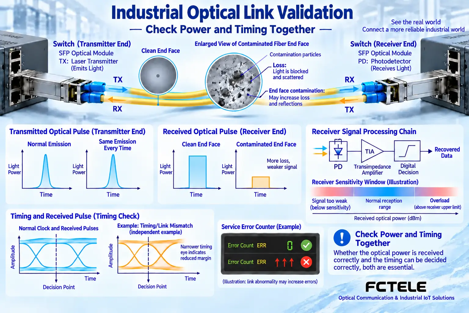
After physical link establishment, test actual load, loss, errors and continuity, and observe recovery. Keep before-and-after records rather than accepting the link on LEDs alone. If support is unclear, return to a verified configuration for diagnosis instead of repeatedly trying unknown parts. The question is whether the complete new link has documented support and passes validation, rather than whether single-mode sounds more advanced.
References:FCTEL DIN-rail industrial switch category;Sixteen-Gigabit-copper/eight-Gigabit-SFP product details;Cisco fiber-type and special-condition examples in optical module data sheets. Third-party capabilities are not FCTEL model specifications. Figures illustrate generic mechanisms, not product photographs or measured specifications.
Translated from the Chinese technical article. Source first published: 2020-11-30. Source last revised: 2026-10-13T14:51:17+08:00. Read the Chinese source
