


Port errors or high CPU utilization do not immediately prove hardware damage. Check what is counted, when it happened and how counts change. Then separate received bad frames, valid frames discarded by queues or policies, and control traffic handled by the CPU. Different causes require different action; one generic command or a restart cannot replace diagnosis.
1. Understand what a counter records
An Ethernet frame is a data unit with hardware addressing and integrity-check information. Interfaces may count reception, transmission, frame-check errors, discards, rates and link changes. An errors field often aggregates several subcategories, and models differ in scope. Consult the actual manual for port, direction, units and included categories.
A large lifetime total does not establish an active fault. Record the observation interval, changes and contemporaneous traffic, comparing normal and abnormal periods. Restarting, clearing counters or counter rollover also changes readings. Clearing without saving evidence can make intermittent problems harder to investigate.
An error increasing under load establishes a possible relationship, not necessarily load as its cause. More traffic can expose a cable problem too. Put endpoint logs, interface states and application responses on the same timeline. Seek a repeatable relationship instead of replacing a switch based on one screenshot.
2. Investigate frame-check failures along the input link
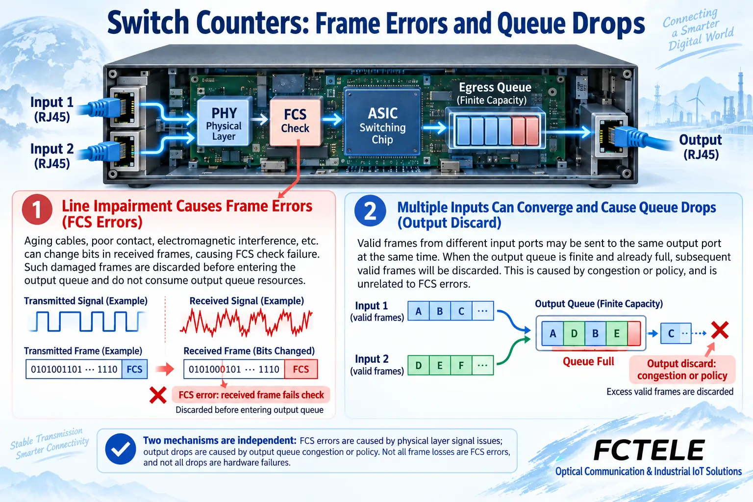
FCS, the frame check sequence, lets a receiver check for detectable transmission errors. Failure establishes a bad received frame; it is not another name for a full output queue. Cabling, connectors, interference, the peer interface or negotiation can contribute. Use other states to narrow the possibilities.
In an authorized maintenance window, compare a known-good short jumper and verify actual speed and duplex at both ends. Then investigate permanent cabling and terminations. Eight conductors being continuous does not certify electrical transmission performance. For fiber, check modules, end faces and transmit/receive conditions rather than applying copper test methods to glass.
3. Interpret duplex and frame sizes in context
Full duplex lets both ends transmit and receive simultaneously; traditional half duplex uses shared transmission conditions and a different mechanism. Inconsistent endpoint settings can degrade performance. Start with manufacturer-recommended auto-negotiation rather than forcing one end while leaving incompatible settings at the other. Do not apply every old Fast Ethernet half-duplex rule to Gigabit interfaces.
Some interfaces report collisions, fragments, undersize or oversize frames. These are diagnostic clues, not unique signatures of a damaged component. Tags, maximum permitted size and counter definitions affect length interpretation. Exceeding a number in an old tutorial does not prove a failed NIC, and an alignment error does not mean an arbitrary even-number-of-bytes rule.
Commands and fields quoted in old articles belong to particular platforms; FCTEL models need not expose the same names. Find equivalent information through the current model’s Web interface, CLI or management tools. The purpose is understanding evidence, rather than constructing one script of commands for all brands.
4. Why valid frames can also be discarded
Several inputs converging on one egress can deliver more frames briefly than that egress can transmit. Frames wait in finite buffers; sustained excess demand can produce discards. Low average utilization does not exclude a short burst, because a long averaging interval hides brief peaks.
Output discards may also follow configured rate limits, queue policies or other implementation-specific conditions. Confirm the counter’s definition. A larger buffer cannot solve continuous demand above egress capacity and may add delay. Assess uplink capacity, transmission scheduling and necessary traffic management rather than merely replacing a cable.
Applications respond differently to loss. TCP can retransmit and adjust sending behavior. UDP itself lacks the same reliability mechanism, but an application using it can implement its own recovery. UDP does not mean every application has no compensation. Acceptance must examine actual responses and data completeness.
5. Separate CPU activity from hardware forwarding
Many managed switches use a dedicated switching chip for most ordinary forwarding, while a CPU handles management, control protocols and selected software-processed frames. Forwarding and control planes interact, but not every endpoint frame necessarily passes through the CPU. Architectures differ, so interpret the actual model rather than making an absolute rule.
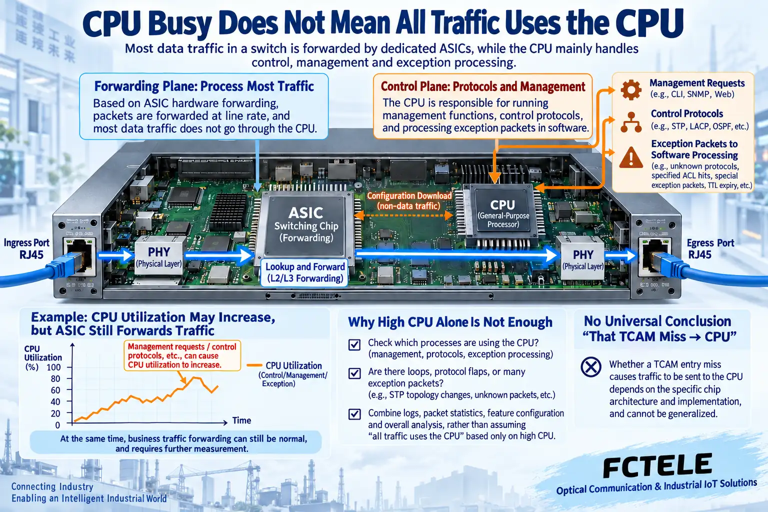
CPU activity may rise because of management requests, protocol changes, abnormal frames or software problems. That can affect management and protocol responses without proving failed hardware forwarding. Check the normal baseline, duration, processes or frame classes, and whether applications are affected. Temporary application success is not a reason to ignore persistent abnormal load either.
Control-plane protection and exception statistics on some platforms do not establish identical FCTEL menus. Do not copy third-party limits or disable protective rules without confirming support. Incorrect changes can disrupt necessary control communication. Production work needs backups, authorization and recovery paths.
6. Collect evidence using documented product capabilities
The corresponding FCTEL lightly managed DIN-rail industrial switch page explicitly lists port traffic statistics, mirroring and storm control. Statistics help observe change; mirroring copies selected traffic for analysis; suppression limits configured categories. None repairs physical-layer errors. This describes only the functions confirmed on that product page.
Before procurement or diagnosis, confirm required error subcounters, time resolution and logs. Mirror-output or analyzer overload can lose copies, so a smaller capture count does not directly establish application loss. Internal CPU queues, hardware tables and protective mechanisms need more detailed model documentation or vendor support; do not infer them from an overview.
7. Connect each conclusion to its evidence
If input errors stop increasing after a qualified jumper substitution and traffic recovers, record the link-related evidence. If valid-traffic peaks correspond to egress discards, investigate capacity and policy. If management alone is slow while applications continue, investigate management and forwarding separately instead of treating them as one cause.
After treatment, validate sustained applications, normal peaks and approved recovery cases. Preserve before-and-after counters and configuration. Escalate unexplained persistent errors, restarts or hardware alarms to the supplier. State which conclusions were verified and which remain hypotheses, so the next maintainer can reproduce the observation rather than inherit only restarted and now normal.
References:FCTEL product statistics and mirroring functions;Interface error counter definitions;Negotiation mechanisms;Control-plane and CPU diagnosis. Third-party documents verify mechanisms, not universal FCTEL commands. Figures are generic illustrations, not product photographs or measurements.
Translated from the Chinese technical article. Source first published: 2020-03-16. Source last revised: 2026-10-13T14:51:17+08:00. Read the Chinese source
