


Can an adapter solve a multimode cable meeting a new single-mode route, insufficient cores or a span beyond existing optics? Generally not. Mode conversion changes optical conditions between segments, a repeater receives and retransmits, and wavelength-division multiplexing lets different wavelengths share fiber. They can form a solution, but a vague additional-features label must not hide the required equipment and matching conditions.
Separate three extension requirements
Different fiber types need a suitable optical-to-optical conversion arrangement. Excess loss requires a different optical configuration or a powered intermediate node. Scarce cores may justify BiDi or wavelength multiplexing. Port shortages, incorrect VLANs and duplicate endpoint addresses are not repaired by changing fiber mode.
An ordinary Ethernet converter usually connects copper and fiber. Multiport products may switch frames, but the name does not establish architecture. Specify endpoints, speed, each segment’s fiber and the required function before choosing a dual-optical converter, back-to-back electrical/optical converters or a switch with suitable modules.
Changing mode means receiving and transmitting again
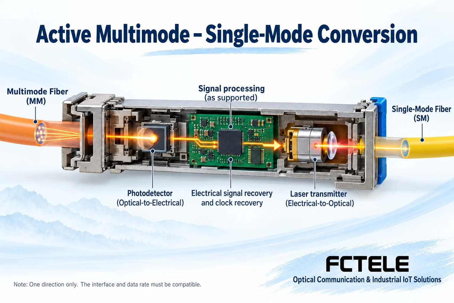
A common active arrangement receives the first span at its required fiber, wavelength and rate, converts the signal into electrical information, and drives a separate transmitter for the next span. Each optical interface matches its own peer; an electrical connection or internal processing transfers the information between them. Mechanical connection alone does not establish optical compatibility.
For Ethernet, a suitable dual-optical product may work, or two converters can form an intermediate point if their copper interconnection and speeds are supported. Recoding, reshaping and clock recovery depend on architecture. Protocol-transparent products also have rate windows and protocol limits. Dual SFP does not mean every signal is supported.
A repeater does not simply add distance labels
Receiving and retransmitting divides a route into separately budgeted spans. Each still needs suitable power, overload limits, fiber, dispersion or bandwidth. Joining equipment with particular distance labels does not guarantee double reach in every environment. Connector loss and engineering margin remain necessary.
The intermediate node adds power, equipment, enclosure and maintenance requirements. At a remote site, reliable power may be harder than fiber. Include processing delay, management visibility and recovery, and compare whether different end optics would be simpler. Test each span before testing the complete application, rather than accepting an intermediate LED.
How WDM shares fiber between services
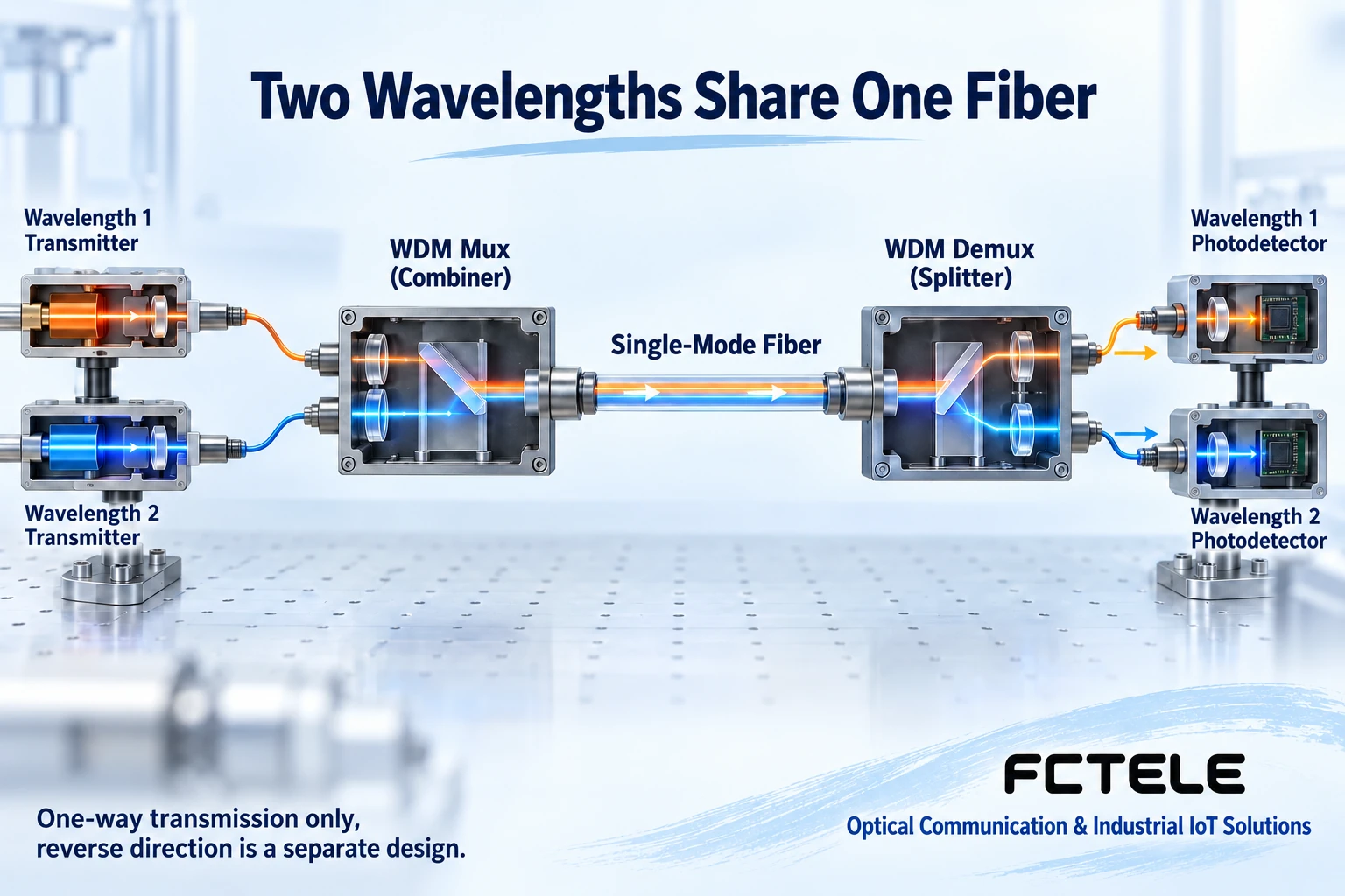
Wavelength-division multiplexing, or WDM, uses different wavelengths as optical channels. A multiplexer combines signals matched to its channel plan into one core; the remote demultiplexer directs each wavelength to its receiver. Separation occurs optically. Connecting ordinary network ports to a passive splitter does not create independent Ethernet channels.
Transmit wavelengths must fit the multiplexer/demultiplexer channels, with bandwidth, temperature drift and connections checked. Include their insertion loss in the budget. CWDM and DWDM channel plans are not interchangeable merely because both use wavelengths. Match both multiplexing devices, optical modules and application mapping. Bidirectional service additionally needs an explicit reverse wavelength/core arrangement.
Single-fiber BiDi is not the same as multichannel WDM
Common BiDi uses complementary wavelengths for opposite directions of one connection. Multiservice WDM can use more channels for multiple connections. Both exploit wavelength differences, but endpoint pairing, core use and channel plans differ. A single-fiber converter does not automatically connect to arbitrary CWDM equipment.
Separate optical-channel capacity from application throughput. Combining wavelengths does not increase either channel’s individual rate. Equipment that first aggregates electrically and sends over one optical channel can still have an uplink bottleneck. Plan from each application’s peaks, sustained load and allowed interruption, not port counts alone.
Validate a migration span by span
Suppose an old factory retains multimode fiber internally while a new building route uses single-mode. List existing optical standards and the new span’s requirements. Confirm the converter covers both interfaces and application speed. Test the old multimode equipment to the conversion point and the new single-mode span separately. Then carry actual applications across the whole route while observing queues, loss, errors and delay. One reachability test is insufficient.
FCTEL’s one-optical/four-copper Gigabit external-power converter demonstrates an electrical-access/optical-uplink product structure. It can inform an intermediate electrical connection, but does not establish dual-optical mode conversion, CWDM or unrestricted repeating. Submit fiber types, standards, rate and topology for vendor configuration confirmation when those dedicated functions are needed; do not infer them from another model.
Fault isolation and maintenance boundaries
For a repeated link, compare each span’s power and equipment state with the last good segment records. If only one WDM application fails, check its wavelength, patching and receive range. If every channel fails, inspect shared fiber, multiplexer connections and common power first. Substitute one variable at a time and preserve the channel map, preventing new faults from swapped cores.
Clean end faces, maintain margin and control enclosure temperature. Never look into ports or connect an unknown source to an unsuitable meter range. Back up settings and prepare rollback before replacing equipment. Switch supported backup paths according to maintenance procedure; do not experiment with electrical connections that could loop a running industrial network.
References:Perle dual-SFP and wavelength conversion documentation supports the generic active-conversion explanation;FCTEL one-optical/four-copper product details provide the port-combination example only. Figures illustrate generic mechanisms rather than model capability evidence or field measurements.
Translated from the Chinese technical article. Source first published: 2021-03-19. Source last revised: 2026-10-13T14:28:14+08:00. Read the Chinese source
