


Upgrade goal: let two LANs use existing E1 channels
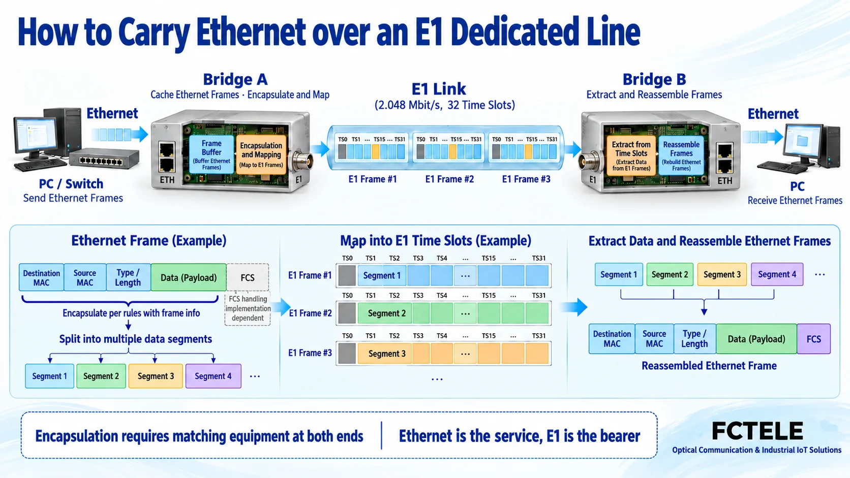
When there is a working E1 leased line on site, but new service equipment at both ends provides Ethernet interfaces, you can evaluate an Ethernet-to-E1 converter, also often called an E1 Ethernet bridge. Place one matching device at each end, send Ethernet frames into the existing E1 circuit, and restore them as Ethernet frames at the far end. The service interface is updated, but the bearer resource in the middle is still E1.
This path is exactly different from E1 over IP: this article is about “Ethernet service passing through an E1 channel,” while circuit emulation is “E1 service passing through an IP network.” If the original service equipment still outputs E1, but the middle has already been changed to IP, you cannot directly buy a bridge according to this article’s solution. First determine the service direction, so you can clearly separate reusing old lines from migrating equipment.
How Ethernet frames enter a continuously running E1 circuit
A computer or switch sends data frame by frame. There may be idle gaps between frames, or there may be continuous bursts. The bridge receives frames and temporarily stores them, then organizes the data according to the encapsulation method supported by both ends, and maps it to available E1 time slots or channels. The far end extracts the data according to the same rules, reassembles the frames, and then sends them to the target network through the Ethernet interface.
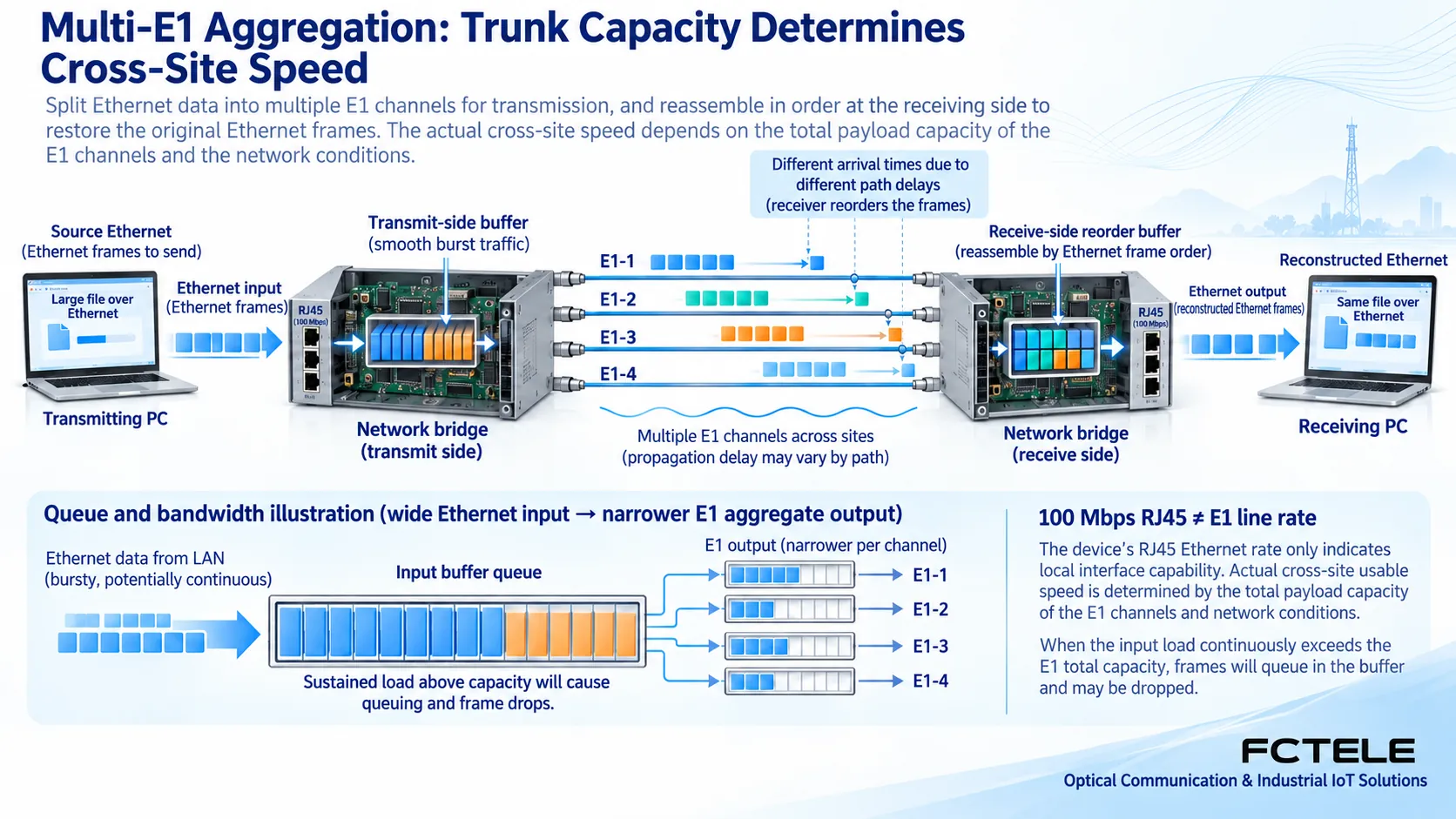
E1’s continuous rhythm is not the same as Ethernet’s bursty input. Buffering can absorb some instantaneous bursts, but its capacity is limited. When the long-term input exceeds the available bearer capacity, the queue will grow, and frames may then be dropped. Therefore, the electrical port connection speed, line capacity, and actual application throughput need to be checked separately as three concepts.
A 100 Mbps electrical port will not turn a single E1 into a 100 Mbps leased line
The E1 line rate is 2.048 Mbit/s. After framing, overhead and available time slots still need to be considered according to the service mode. Some Ethernet mapping devices give a single-E1 available channel capacity of 1.984 Mbit/s, that is, thirty-one 64 kbit/s time slots, but this value cannot be applied to all framing and signaling modes. Service packet headers and other overhead also occupy part of that capacity.
The Feichang Technology FCC-E16F4 details list a single-channel capacity of 1984 Kbit/s, with a maximum of sixteen E1 lines combined. The 7.936 Mbit/s corresponding to four lines is a calculated value of channel capacity under that configuration, not a guaranteed net throughput that the application can obtain. Frame length, encapsulation, test method, and on-site bit errors all affect the final result. The 100 Mbps interface on the bridge panel only describes the local access condition.
Why multi-line aggregation requires reordering and absorbing path differences
Using multiple E1 lines together usually involves inverse multiplexing: distributing a larger service across several smaller channels, and then restoring the original data relationship at the far end. Here, “inverse” emphasizes splitting and reassembly; it does not mean reversing the signal transmission direction. If different E1 lines travel over different transmission paths, their arrival times may differ, and the receiving side must handle this difference within the supported range.
The Feichang model documentation involves GFP, virtual concatenation, and LCAS. GFP is the Generic Framing Procedure, responsible for the corresponding encapsulation; virtual concatenation combines several channels; LCAS is used to adjust the capacity of the relevant combination. These names describe different stages. They cannot be lumped together as one protocol, nor can it be inferred that any vendor and any encapsulation can automatically interoperate.
After selecting the equipment, you need to check the firmware at both ends, the encapsulation mode, the number of E1 lines involved, and the channel allocation. If one line fails, whether the system continues transmission with reduced capacity, whether it alarms, and how it rejoins should be tested according to the specific configuration and manual. Even if the connection still exists after reducing channels, the traffic it can carry will also decrease. You cannot just check that the network port light is still on.
What management, service, and the old transmission network each need to confirm
The management port is used to configure and query the device, while service frames pass through the service forwarding path. Setting an IP address on the management port does not mean the device is performing Layer 3 routing for the user’s network, nor does it replace communication design for the remote subnet. A transparent bridge and a router have different roles. Whether the user-side subnet, broadcast domain, and VLAN are suitable for this bearer should be determined by the complete network plan.
On the E1 side, you need to check the 75-ohm or 120-ohm interface, framing and CRC settings, clock source, and actually available time slots. If circuits are allocated through transmission equipment in the middle, you also need to confirm that the end-to-end channel connection is correct. The fact that the bridge configurations at both ends look consistent does not prove that the carrier or on-site transmission network has delivered the same group of circuits to the correct locations.
The network management, number of interfaces, and fault handling of a multi-E1 bridge may depend on options. The FCC-E16F4 details state that an independent SNMP management module can be configured, so SNMP cannot therefore be written as a basic function of all E1 converters. The procurement list should clearly state the model, ordered version, required alarms, and maintenance method together.
First test capacity according to the service, then decide whether it is worth using the old line
Monitoring, low-speed data exchange, and similar needs can be considered candidates, but you should first measure normal traffic and burst peaks, calculate the available bearer, and leave margin for protocol overhead and growth. If the goal is large amounts of video or continuous high-speed file transfer, old E1 resources may not be suitable. You should not promise that new services can be supported just because lines already exist. This is an evaluation approach, not a fictional customer case.
Before activation, save the configuration and agree on a maintenance window. First lock one E1 line and one encapsulation on a short link or in a test environment, then gradually add the remaining channels. Formal acceptance should simultaneously check E1 bit errors and alarms, Ethernet frame loss, bidirectional services, and latency under actual load. The test report must clearly state frame length, traffic direction, and number of channels; otherwise, different throughput numbers cannot be directly compared.
Finally, under the permitted maintenance conditions, verify single-channel failure, traffic after capacity reduction, and the recovery process. Exit test mode, then confirm the service mapping and alarm status. The value of an upgrade is to reasonably use available resources and match interfaces with channels; the converter itself cannot add line capacity that does not exist, nor can it solve long-term overload by buffering.
Documentation note: The principle diagrams have been checked against technical content and are used to explain general mechanisms. They are not product photos or measured records. Specific interfaces, modes, and capabilities are subject to the selected model, version, and on-site verification.
Verification references:ITU-T G.703: Physical and electrical characteristics of digital interfaces
ITU-T G.704: Synchronous frame structures
ITU-T G.7041: GFP
ITU-T G.7042: LCAS
Feichang Ethernet-to-E1 category
Feichang 16E1-4FE bridge FCC-E16F4
Translated from the Chinese technical article. Source first published: 2023-12-12. Source last revised: 2026-10-13T14:18:10+08:00. Read the Chinese source
