


The same pair of telephone optical transceivers can carry multiple phone lines. It does not directly mix several people’s voices together, and it does not need to assign a different color of light to each phone line. A digital telephone optical transceiver processes each voice channel and call state separately, organizes the data into a single transmission bitstream according to agreed rules, and the other end recognizes the rules and sends the content back to the corresponding phone line. Understanding this process is necessary to judge what “how many phone lines,” “one fiber,” and “how much bandwidth” each actually mean.
First, distinguish between voice and call state
Imagine a factory office has three analog extension lines that need to be extended to a remote duty room. The three analog extension ports of the PBX connect to the near-end device, and the three telephone ports at the far end connect to three phones. Each line is an independent call; you cannot connect three telephone lines to one port to increase capacity. Both ends usually have both transmit and receive functions, so the terms “transmitter” and “receiver” should not be understood as one end always only speaking and the other end always only listening.
Voice is an electrical signal that changes over time, while off-hook, on-hook, and incoming ring are call states. If only voice is sent, the phone may still be unable to receive calls or release properly. The device needs to detect the local state, transmit it to the other end, and then the telephone interface at the other end produces the corresponding action. Ringing voltage is not transmitted directly along the fiber; the fiber carries transmission information, and the far end restores line conditions through local power and interface circuits.
How analog voice becomes digital data
Sampling can be understood as recording the value of the voice waveform at each moment according to a fixed rhythm; quantization and encoding then represent these values as numbers. After voice enters the codec circuit, it forms digital data arranged in sequence. The receiving end restores it according to the same rules and then sends it to the telephone line through the interface circuit. Input filtering, sampling, encoding, and output restoration all affect the voice, so “digital transmission” cannot be treated as a guarantee of no error.
Using G.711 voice encoding as a teaching example, 8000 samples per second and 8 bits per sample correspond to 64 kbit/s of voice encoding data in each direction. This is only to explain the calculation method; it does not prove that any telephone optical transceiver uses this encoding, nor does it mean that the entire optical link only needs this rate. The encoding method, additional signaling, frame structure, and overhead of an actual product must be checked in the corresponding model’s documentation.
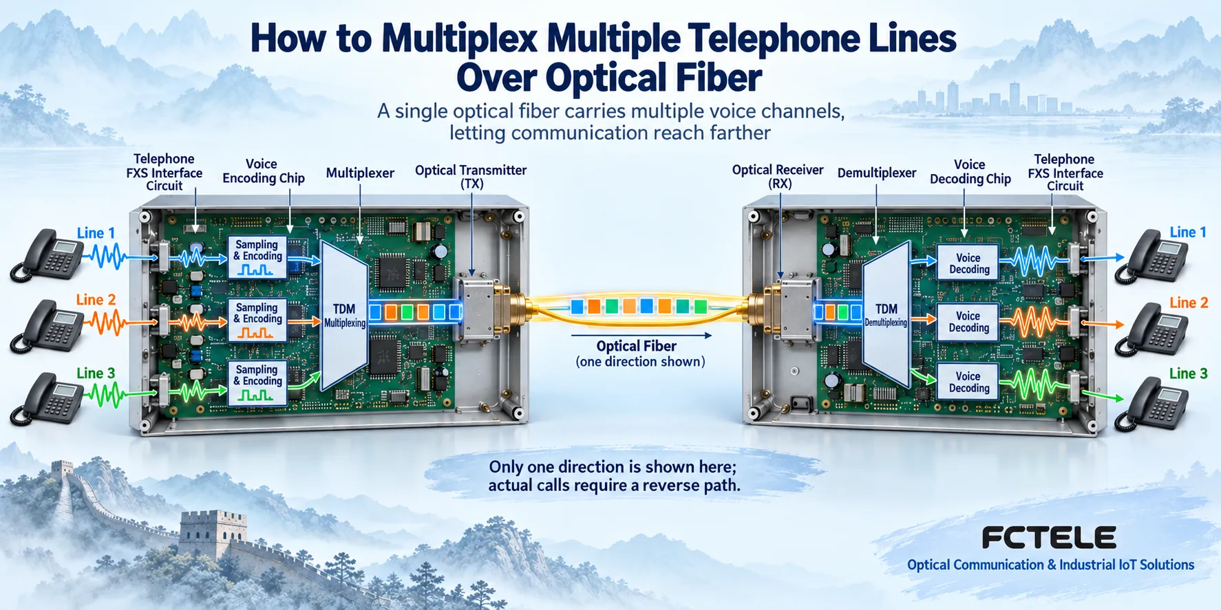
Why time-division multiplexing does not mix three voices together
Time-division multiplexing means letting multiple channels use transmission time in an agreed order. You can imagine a repeating data frame as numbered trays: parts of the data for phone line one, two, and three enter their respective positions, and the receiving end recognizes the frame boundaries and the purpose of each position, so it can extract them separately. An actual frame may also contain synchronization, control, detection, and other information, and is not necessarily the simplified three slots shown in the figure.
This method does not require the first user to finish speaking before the second user can speak. Each voice channel is processed continuously, and the transmission equipment organizes data on a finer time scale, so multiple users can talk at the same time. Taking turns to arrange data in the bitstream is completely different from users taking turns using the telephone. The buffering and restoration process at the receiving end also has timing requirements, so “simultaneous calls” cannot be used to conclude zero delay.
Demultiplexing is the reverse process. The receiving end first restores the transmission data and synchronization, then extracts the content belonging to each channel according to the channel rules and sends it to the corresponding decoding and telephone interface. If the channel mapping at the two ends is inconsistent, dialing one number may ring another phone, a channel may have no sound, or calls may be connected to the wrong line. A physical optical link being able to connect only proves that the common transmission part meets certain conditions; it does not mean that channel correspondence and call services are already correct.
Wavelength division multiplexing solves a different layer of problems
Wavelength division multiplexing lets light of different wavelengths share a fiber. Common uses include combining different optical channels together, or distinguishing the two transmission directions in a suitable single-fiber paired device. It is not the same layer of mechanism as how telephone channels are arranged inside the digital bitstream. Multiple phone lines can still be multiplexed inside one optical channel, so “one phone line per wavelength” cannot be used as a general explanation for ordinary telephone optical transceivers.
Dual-fiber devices usually connect the local transmit to the remote receive, with the two directions traveling over their respective fiber cores; single-fiber bidirectional devices require checking the paired model, transmit and receive wavelengths, and device interoperability conditions. The figure only compares principles and does not assign a uniform wavelength to all products. The same optical connector and the same nominal distance cannot guarantee interoperability between two devices from different transmission systems.
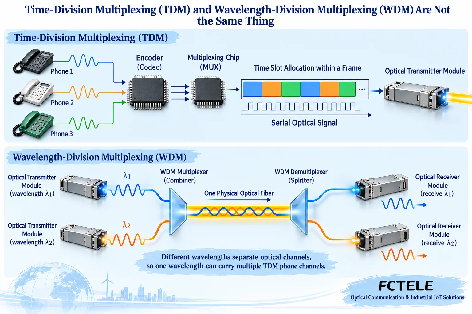
How to check telephone line count, optical rate, and service bandwidth
If an example system has sixteen lines and each line uses 64 kbit/s voice encoding per direction, then the voice encoding data totals 1024 kbit/s. Transmission also has overhead such as framing, synchronization, and signaling, so this total cannot be used directly to determine the optical module rate or device capacity. If another encoding is used, or Ethernet or other services are added, the resource organization may differ, and the same simple multiplication cannot continue to be applied.
Fixed-channel devices may not let users freely adjust the bandwidth of each call. Free capacity on the optical port does not necessarily mean more phones can be connected: you also need enough telephone interfaces, codec and processing resources, matching configuration at the far end, and an expansion method explicitly supported by the device. For multi-service units with network interfaces, you cannot infer from the interface rate alone that telephone and network services can simultaneously reach all their nominal capabilities.
A telephone optical transceiver is also not naturally equal to a VoIP gateway, SDH equipment, or a switch with QoS scheduling. Ordinary analog line extension, voice over IP access, and E1 access require separately confirming interfaces and protocols. When purchasing, you should state whether you want to extend analog extensions or connect to an IP telephone system, and then have the supplier provide a corresponding solution, rather than only asking how many kilometers it can transmit.
Verify multiplexing results with three simultaneous calls
First, on a short link that meets the received optical power requirement, test one channel using a paired device, a known-good PBX extension port, and a known-good telephone. Then add channels one by one and record the correspondence table of near-end ports, extension numbers, and far-end ports. Initiate calls one by one and confirm that only the target phone rings; after connection, check two-way voice, then hang up from each side separately and observe whether the line releases correctly.
Then let multiple channels talk at the same time and check for crosstalk, wrong ringing, one-way no sound, or one channel being interrupted while other phone lines are in use. Caller ID, fax, and other signaling functions need to be verified separately; one ordinary voice call cannot replace all compatibility tests. If all channels are abnormal at the same time, first check the common power supply, optical path, and synchronization; if only one channel is abnormal, locate the problem by swapping in a normal phone, a short cable, and the corresponding port.
Do not arbitrarily adjust gain to hide channel or signaling errors. Change only one condition at a time and keep alarms, configurations, and results before and after. Telephone lines may have ringing voltage, and you must not look directly into optical ports; measurement and wiring should follow the device manual and be performed by personnel with the appropriate capabilities. Acceptance should be based on the actual line and service requirements; a principle diagram cannot replace on-site testing.
How to match Feichang Technology product documentation
Feichang Technology Pure telephone optical transceiver series can serve as an entry point for selecting line count and installation form. Among them, the FCP-O16/FCP-S16 desktop product page lists 1–16 FXO/FXS interfaces and network management options. This documentation helps verify port roles and configuration, but it does not prove that the figure uses that model’s actual frame structure or internal circuits. Specific encoding, channel mapping, optical port configuration, and optional functions should be obtained from the corresponding documentation before ordering.
Documentation note: general voice encoding reference ITU-T G.711. The calculations in this article are teaching examples; product capabilities are based on the above official website pages and should be checked against the actual configuration. The two figures are general functional illustrations, not measured results, teardown images, or specific model structures. This article corrects the original description that bound each phone line one-to-one with a wavelength and equated multiplexing with arbitrary capacity expansion.
Translated from the Chinese technical article. Source first published: 2024-12-06. Source last revised: 2026-10-13T13:49:23+08:00. Read the Chinese source
