


Telephone services can reach remote sites by borrowing an existing SDH network, but the optical port of an ordinary telephone optical multiplexer cannot therefore be plugged directly into SDH equipment. A feasible solution must first find a service interface that both sides support, such as E1, and then confirm the line, frame structure, clocking, signaling, and channel mapping. The same optical connector, the same wavelength, or both having SFP installed only indicates that some physical conditions are similar; it does not mean the services can interoperate.
First ask clearly: extend telephone service, or connect to SDH?
If there is already usable fiber between two buildings and the customer only needs to send analog extensions to the other building, a pair of telephone optical multiplexers can be used. The two ends organize voice and call status in the way agreed by the manufacturer, and SDH is usually not required. If the only option is to lease an existing SDH circuit from an operator or an organization, then it is necessary to confirm which interface is delivered to the customer. Delivering an E1 electrical port and delivering a bare fiber are two different resources and cannot use the same connection method.
SDH is the Synchronous Digital Hierarchy. It is responsible for loading information from different tributaries into a specified transmission structure and for carrying and cross-connecting it in the network. It is not responsible for providing ringing to analog telephones, nor does it automatically understand the private optical code stream of any telephone optical multiplexer. Compare the equipment to a transport stage: the telephone interface first organizes the user service, and SDH then carries goods that conform to the interface agreement; this analogy does not mean that any packaging can be loaded directly.
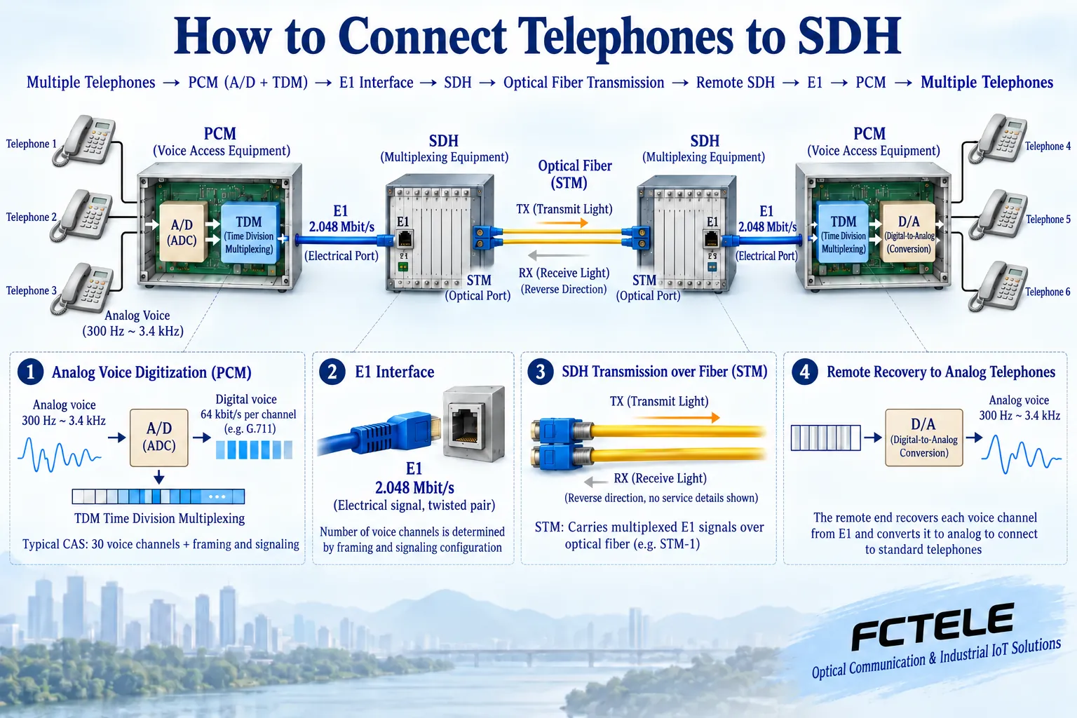
From telephone to E1, what happens in between
Analog voice is an electrical signal that changes over time. PCM access equipment samples and encodes it, organizing each channel’s data in time order. Off-hook, on-hook, and ringing are call states and must be transmitted through an agreed signaling mechanism. The remote end must recover both the sound and the correct telephone line actions; otherwise, sound may be heard but incoming calls or release may not work properly.
The nominal line rate of E1 is 2.048 Mbit/s. Taking a common framed structure as an example, one frame has 32 time slots, each time slot has 8 bits, and the frame repetition rate is 8000 times per second. This explains how data is arranged; it does not equal 32 telephone channels. A typical channel-associated signaling configuration uses TS0 for framing-related information, TS16 for signaling, and the remaining time slots carry voice channels, commonly 30 channels. Other signaling, unframed data, or specific equipment configurations cannot directly copy this number of voice channels.
The two access devices must also use matching voice encoding and channel mapping. If the first channel at the near end is placed into a certain time slot, the far end must extract it from the same service position. If only the line alarm disappears, the channel may still be connected incorrectly. Analog interfaces should also be distinguished as FXS and FXO: the former provides line conditions to connect a telephone, while the latter uses a line to connect to a PBX extension port; one cannot judge only by the RJ11 plug.
How E1 enters SDH, rather than “changing to the same kind of light”
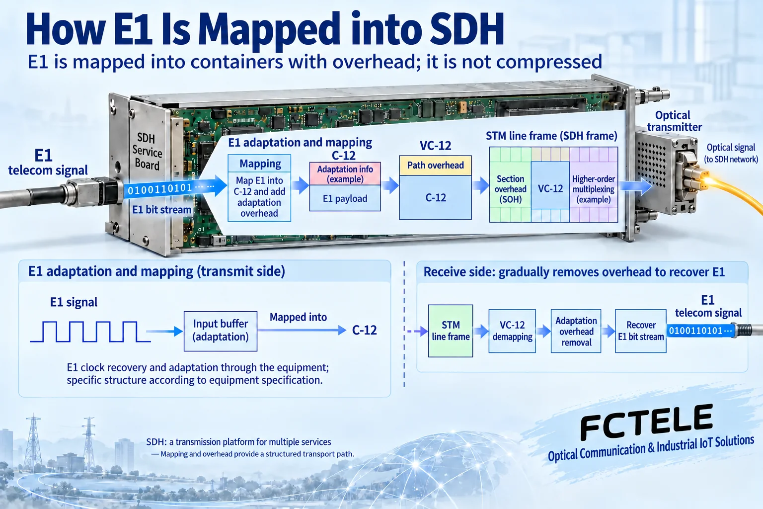
After an SDH node receives an E1 tributary, it maps the tributary into the corresponding container according to the standard. A common 2.048 Mbit/s tributary can be carried by VC-12 and then organized into a higher-layer SDH structure. The line simultaneously contains overhead required for maintenance, positioning, and management. The remote node extracts the tributary according to the corresponding cross-connection and then restores E1 to the access device.
Mapping is not compressing voice to make it smaller, nor is it changing an ordinary telephone optical port into an STM optical port. The SDH line port transmits the specified line frame; the paired optical port of the telephone equipment may use a different frame structure. SFP is only a package form for a pluggable optical-electrical module; having an SFP installed does not prove that the whole device implements the SDH line protocol. Unless the manual clearly states that the device has an interoperable SDH interface and configuration verification has been completed, interconnection should be made from a confirmed tributary interface.
Five boundaries that must be checked before commissioning
The first is the electrical interface. E1 may use a 75-ohm unbalanced or 120-ohm balanced interface; connectors, impedance, and wiring should be selected according to both manuals. One cannot casually splice them just because both are labeled E1, nor use ordinary network cable wiring to replace the pin assignments specified by the manufacturer. When impedance conversion is needed, use an adapter that meets the equipment requirements.
The second is the framing setting. The framing or unframed mode, CRC configuration, and time slots used must be consistent on both sides. The third is signaling. Channel-associated signaling, common channel signaling, and transparent transmission schemes have different requirements; these should be confirmed by the service side, and the equipment supplier should provide the corresponding settings. The fourth is clocking. A plan must be made for who provides the clock and who recovers or follows the clock, to avoid both ends waiting for each other or multiple free-running clocks causing long-term slips. A slip is a manifestation of a shift in the relationship between received data and the clock; it may cause short-term voice abnormalities and cannot be concealed only by restarting.
The fifth is network cross-connection. It must be clear which remote E1 the local E1 is actually connected to, and which tributary number and container are used. A normal optical path at a node does not prove that this customer service has been commissioned. Line alarms, tributary alarms, bit errors, channel correspondence, and call results should be recorded separately.
Using an eight-extension example to understand acceptance
Assume a customer has eight analog extensions that need to be extended to a remote site through an existing E1 circuit. First confirm that the access devices at both ends support eight interfaces and the required signaling, and then have the SDH network provide a matching end-to-end E1 path. Which voice time slots are specifically used is determined by the equipment configuration; ports without telephones connected cannot be casually treated as reallocatable data resources.
During commissioning, first verify the access devices and telephones in a test environment, and then verify the E1 path. Record the near-end port, extension number, time slot, and far-end port for each channel; separately check dialing, ringing, two-way voice, and on-hook release on both sides. After that, perform an eight-channel concurrent test and continuously observe E1 bit errors, synchronization, and alarms. Caller ID, fax, and protection switching are additional acceptance items and cannot be replaced by a single successful voice call.
If all voice channels are abnormal at the same time, first check E1 synchronization, framing, power supply, and the common bearer; if only one channel is abnormal, then check channel mapping, signaling, telephone line, and telephone. Loopback testing may affect services and must be implemented according to the manual within an approved maintenance window; after testing, remove the loopback to avoid leaving the test state in the production system.
How to use Feichang Technology equipment materials
Feichang Technology official website’s FCC-CS30 No. 1 signaling (channel-associated signaling) E1 PCM product information describes optional 1 to 30 voice channels and channel-associated signaling configuration. This type of material is suitable for checking the telephone-to-E1 access stage; it cannot be used to claim that the device’s ordinary optical port is directly compatible with all SDH nodes. When purchasing, submit the SDH delivery interface, framing, impedance, clocking, and signaling requirements to the supplier, and obtain interconnection instructions for the specific model.
After understanding this path, selection is no longer just about asking distance and wavelength, but about confirming “how the telephone becomes a tributary, how the tributary passes through the network, and how the remote end restores the same service.” If any layer lacks evidence, “seamless compatibility” cannot replace testing.
Reference note: interface and frame structure references ITU-T G.703,G.704 and G.707. The two figures are general principle diagrams, not teardown diagrams or measured results. This article corrects the original statement that inferred SDH compatibility from SFP, optical fiber connectors, or a single rate.
Translated from the Chinese technical article. Source first published: 2024-11-11. Source last revised: 2026-10-13T13:49:23+08:00. Read the Chinese source
